How far can I push 6xTO220 controller

LuboN

100 mW
Joined
Mar 8, 2015
Messages
46
Location
Slovakia
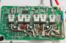
Recently I have changed mosfets in my Golden Motor Magic controller (marked as 30/50A 1kW max and used with Golden Motor Magic Pie 2 motor). Originally there were six IRF1407 and I replaced them with IRFB7730. Before modding it maxed continuous at about 27A/1500W (14s LiPo battery) without any problems. I have beefed copper bus and traces on PCB, added thermal compound on the fets (originally it was only between insulator sheet and heatsink) and also slightly changed shunt value. Now it goes up to 60A/3kW and the temperature (I have installed temperature sensor on the heatsink directly where the fets on the other side are) stays fairly low all the time (mostly in 20-30°C region, never seen over 40°C). I have to say that we have temperatures between 5-15°C outside right now and the controller is well placed for good cooling.
So, what do You think about this build and what opinion do You have about pushing it higher? Before increasing the current I am prepared to beef everything even more and to add some capacitors close to the fets and also to the supply line near the controller input (there is no space in the controller for electrolytic caps). I don´t think heat is an issue now, I only fear some other problems. It would be great to hear someone more experienced in this stuff before I learn it the hard way...
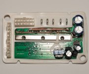
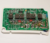
Adding some photos to get you in picture:
 

Attachments

  • DSC_7719.jpg
    DSC_7719.jpg
    185.5 KB · Views: 797
  • DSC_7723.jpg
    DSC_7723.jpg
    229.1 KB · Views: 797
SjwNz, thank You for Your suggestion, I will consider it while adding arduino module on my bike (actual temp. sensor is too bulky to fit directly on the fet). With arduino I can use small thermistor like I have already added to the windings of my motor (bought 10pcs so I have plenty). With the new fets the controller is running cooler (and before the swap the temp. sensor was on the corner of the controller, away from the place where fets are), so I was thinking the fets should also run cooler. I understand that it would be the power bursts that could get it out of safe operating area. Temp probe directly on the fet will help to see what happens. Do You think the temperature is the only concern in this setup?
 
If you are seeing 60amps been pulled from the battery then the phase currents will be much higher, so it could easily be around 100 to 150amps
but with out measuring the phase I am guessing . I think your fets are rated for 174amps at 100degC but I wouldn't run them at that current and you maybe very close to the limits as 3kws from a to-220 based controller is pretty good. I am using the TO-246 package which has a better Thermal Resistance so is able to
get rid of the heat from the Mosfets junction better .

Adding more caps close to the FETs may affect the current shunt, so I would try and connect them to the old caps.
If you don't add extra caps, the ones already in the controller will have a short life.

I was using some cheap soil temperature sensor, and the sensor was only 2mm round so I just
glued it the the side of the FET. It was only a temporary thing just so I could get some readings but was very helpful.
 
T0 220 package legs are rated for continuous approx 75A so this would be the max amp no matter what the fet is rated for ( as long as its rated for above 75A anyway ), thats not to say they can be pushed further, but current above the 75a per fet must be kept to a minimum or for very very short periods, Phase currents can get much higher than battery currents so you must also consider this. this is why most of the 6 fet controllers are only rated for maybe 15-20A as it gives wriggle room for a phase current limit of maybe a max of 75A. There is not much you can do with a hub motor to be able to get the phase currents lower quicker as you can not regear a hub motor .. I have ran lyen 6 fet controllers with 3077's installed on a mid drive with 80A battery and 160A phase with out any problems but the bike was geared in such away to bring down the very high currents asap. then you also need to watch the heat :).
 
I have one of these controllers also upgraded with 3077's and beefed up traces. I ran it at 70A peak (average was much lower) and it barely got warm. The only thing that made it noticeable warm was constant acceleration-e-brake (I now believe it's plug braking, not regen!). Someone else blew a standard one at 115A battery.

I wouldn't go much higher due to that mentioned above: phase current will be getting rather high for a single FET. If you want proper long term reliability I wouldn't run it over 30A battery!
 
Many thanks for all this information, surely it will help greatly in my next steps. It is obvious that it can´t handle 100 phase amps indefinitely, but it is able to do it for short bursts and that suits my needs. After playing with motor simulator at ebikes.ca with different motors, main difference in phase amps is between high turn count wound motors and the low ones. So it really helps that I have slow motor. Maybe one day I will try where the limit is, the only way to find it is to break it. Great thing is that this controller is not so expensive (with some chance to repair it after it blows). I have noticed that the best commonly used mosfet is 3077, while I was able to get even better one, the 7730. Not a huge difference, but it helps when going to the edge...
I have noticed that in original datasheet (opened from irf.com) is stated "ID (Package Limited) 195A". This is weird, because there shouldn´t be such a mistake in original "quality" manufacturer like IR, but obviously it sounds unrealistic. But it would be sweet if it could be true :) Maybe I should try to ask IR...
Also, it sound encouraging to hear that the "stock" controller gave it up at 115 battery amps, I won´t expect number that high. And if 3077 can do 80/160, 7730 has to without doubts. The acceleration of the bike is so high that it takes only seconds to get to speed and low amps. Even uphill it has no problem to speed up fast. At higher speeds the power naturally drops and the phase amps are much closer to batt amps, so there should be no problem. According to my temp probe there is no significant heat buildup of the controller heatsink.
 
The package limit current for a FET is something you will likely never even get close to in real life. IIRC it's the maximum current it can take at 10V with junction temperature at room temperature. Even then it's a momentary rating. By comparison, if designing for reliability a limit of 30A per TO220 FET seems to be common.

FWIW, I did at least 1000 miles on my modded GM controller with a lot of it off-road trying to get up short slopes as steep as the bike could manage. Plus a few burnouts. The controller saw a stalled or near-stalled motor plenty of times.
 
Would like to add some info about the controller I modified.
Last year (2016) I was beating the controller all the time, and with its power my riding style changed and I was often riding "motocross" style... And it still works fine! Recently I am modifying next one for my new e-bike, and this time I am bringing it to a higher level. More copper on traces all the way to the point where mosfet legs enter plastic case + additional capacitors and replacing fastons with wires. Actually don´t want to increase the amps because I am switching from Magic Pie motor to Mxus 3K Turbo 4T which means higher phase currents and prolonged periods of high power draw. It should have more torque and output with the same setting. Hope it would hold as good as the first one...
 

Attachments

  • DSC_9857.jpg
    DSC_9857.jpg
    388.8 KB · Views: 1,205
Are you adding more capacitance as a separate module outside the controller casing? I couldn't see any way to fit more inside the case.
 
Yes, there are separate wires soldered parallel to + and - (not visible on photo). I will add a connector (XT60) to connect it to capacitors outside the housing. This way the wires could be short but there will be no problem with disassembling.
 
Back
Top