I have been holding this back only because I don't want any naysayers to call me out before I can prove its worth. I am doing this one open source as well, as a way to "give back" and because the world needs it. The fastest way we can get more EVs on the road is to stop the bull shit with IP. As Elon Musk said having a patent is like having a loto ticket to a lawsuit.
I have had this on the back burner for a good while. But as I wait for some parts for the Leaf inverter I will start a thread on this one.
This is the best way to lay fets out to current share. It solves MANY problems all at once. I will try to work though the start of this over the next couple weeks.
I will do my best to explain as I go.
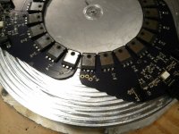
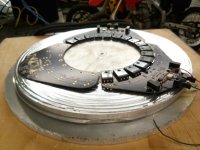
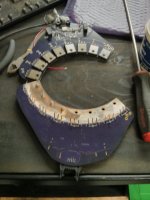
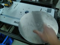
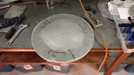
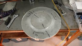
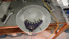
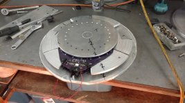
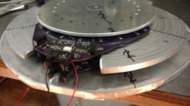
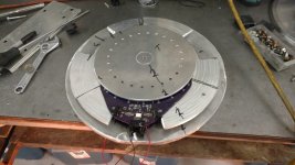
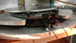
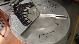
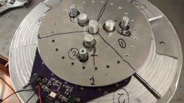
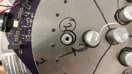
But the basics are The top layer will be the positive buss which is an aluminum circle then a set of boards with high side drains on the top against the aluminum positive buss maybe with some silver grease under that so they conduct well. On the bottom of that is the source trace which is against Aluminum cut into 3 pie shaped pieces. Each of the 3 is 1 phase leg buss. Then under that is another set of boards in the same manner as the first set with the low side fets drains facing up on the top of them to a copper trace on the bottom with the negative buss aluminum circle.
The benefits are as follows.
Perfect (as perfect as possible) current sharing.
Matched, low inductance
Central cap locations which helps reduce inductance between all caps/fets.
Low profile so it will be compact.
Can fit in side a motor if needed.
And many more
All allowing for more power density with hi amperage.
I have had this on the back burner for a good while. But as I wait for some parts for the Leaf inverter I will start a thread on this one.
This is the best way to lay fets out to current share. It solves MANY problems all at once. I will try to work though the start of this over the next couple weeks.
I will do my best to explain as I go.
But the basics are The top layer will be the positive buss which is an aluminum circle then a set of boards with high side drains on the top against the aluminum positive buss maybe with some silver grease under that so they conduct well. On the bottom of that is the source trace which is against Aluminum cut into 3 pie shaped pieces. Each of the 3 is 1 phase leg buss. Then under that is another set of boards in the same manner as the first set with the low side fets drains facing up on the top of them to a copper trace on the bottom with the negative buss aluminum circle.
The benefits are as follows.
Perfect (as perfect as possible) current sharing.
Matched, low inductance
Central cap locations which helps reduce inductance between all caps/fets.
Low profile so it will be compact.
Can fit in side a motor if needed.
And many more
All allowing for more power density with hi amperage.
")