How to isolate (posibly shorted) stator lams?

parabellum

1 MW
Joined
Nov 19, 2010
Messages
2,091
Location
Dominican Republic, north.
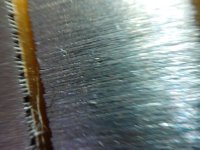
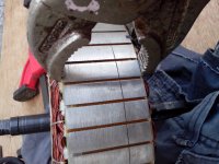
Apparently, this Mxus 3000 hub did not want to fit in to magnet ring and was reduced on belt sander. Just looking at I would expect those lams shorted all around with shavings and act as 1 fat 45mm lam. :lol:
What can I do to have them un shorted again, without disassembling the whole motor?
How bad is it as is?
file.php
 

Attachments

  • IMG_20160613_132138.resized.jpg
    IMG_20160613_132138.resized.jpg
    143.9 KB · Views: 1,555
Miles said:
parabellum said:
How bad is it as is?
The only way to find out is to try it and measure the iron losses, to see how they compare. Is the airgap, as it is now, of a similar width to other Mxus hubs?
I do not know gap size of Mxus hubs, but I have 199.5mm rotor and 198mm stator, so it must be 1.5mm/2.
Can I just try to compress every tooth and hope bridges will not reach lams after releasing?
file.php
 

Attachments

  • IMG_20160613_160636.resized.jpg
    IMG_20160613_160636.resized.jpg
    126.1 KB · Views: 1,541
Miles said:
I think I would test it first, before you risk doing more damage....
Yes, will do that.
Since I am changing phase wires anyway and it is 5t Mxus and is just a bit to slow for my taste, should I connect it in Delta?
Will it mess considerably my timing? :| (cant adjust it on XieChang)
How much efficiency loss can be expected?
 
i have seen that also on a few of my MXUS motors, but could not see higher no-load losses than expected.
however i did not focus on that (thought this won't be a problem) so i did no further comparison..

well, aren't the lams all electrically connected on the aluminum stator??
 
I am not expert in this matter and my words are mostly based on bad memory and some logic.
I imagine this stator as a stack of lams already shorted on inside, where they are pressed on the aluminium cage. In this picture everything still looks right, no loops and current paths this far? (only cage loop but it is far from magnetic hell on the toots)

Now you add sand granule ripped out conductive deformed iron pieces, stretched in sanding process bridging lamination on opposite, tooth side, creating large number of possible current paths of different length (R) all across the stator and cage.
It just seems to cancel out all benefits of 0.35mm lamination and lamination at all.
I hope to come across a study, explaining the impact of given situation to cancel out my paranoia. :)
 
Here is what I mean along with my poor micro photography intent. :D
See produced by sand granule grooves and fold over metal to neighbouring lams, ripped out chunks folded over and pressed in between lams.
Should I also cut a stator apart to see how lams are pressed on the assembly cage? If any interest in that.
file.php

file.php
 

Attachments

  • IMG_20160614_133231.resized.jpg
    IMG_20160614_133231.resized.jpg
    120.7 KB · Views: 1,492
  • IMG_20160614_133246.resized.jpg
    IMG_20160614_133246.resized.jpg
    133.1 KB · Views: 1,492
parabellum said:
Here is what I mean along with my poor micro photography intent. :D
See produced by sand granule grooves and fold over metal to neighbouring lams, ripped out chunks folded over and pressed in between lams.
Should I also cut a stator apart to see how lams are pressed on the assembly cage? If any interest in that.

Hey, did you get further in your experiments ? I'm looking to try something too and actually knowing how I should install laminations would be a great + !
 
Vanarian said:
Hey, did you get further in your experiments ? I'm looking to try something too and actually knowing how I should install laminations would be a great + !
No. I just mounted the motor into 18"x 2.5" motorcycle wheel and on Suzuki AX100 chassis and did ride it 1 time, noticed no excessive loses on unloaded nor loaded run. But I lost all the data, my HD went RIP and I did not touch the moped for over 1/2 year now.
Before that, I just covered stator winding and iron with standard winding varnish (it is king of honey like stuff motor rewinding shops use)
 
I have seen many motors and there's one thing that is sure - lams aren't perfectly insulated - ever. Even if they're not yet mounted on a shaft or in a case, put a multimeter on the edges to measure resistance from left to right and you'll find a high, but not infinite resistance. The reason why we can get away with shorting lams on the OD/ID is the contact patch is very small, thus there is a high contact resistance; the eddy currents that would jump from a lam to the next, can only create a significant flow if the losses per lam are high enough that the voltage differential between the lam "n" and "n+1" is significant enough that it may be able to push a significant current through. Normally, if the stator and rotor are aligned on the same symmetry axis, there just can't be a lot of voltage; couple that with high resistance and lam shorts just shouldn't be an issue. I'd say if you grind, clean as well as you can with wet sandpaper until the lam pack surface is clean, this should remove most of the big contact spots.
 
Back
Top