
You are using an out of date browser. It may not display this or other websites correctly.
You should upgrade or use an alternative browser.
You should upgrade or use an alternative browser.
How to connect ignition wire?
- Thread starter rg12
- Start date
Alan B
100 GW
Through your on/off switch to the battery plus, at least that's the "normal" setup.
Alan B said:Through your on/off switch to the battery plus, at least that's the "normal" setup.
So if I don't use an ignition switch then I should just solder the ignition wire to the battery plus?
Alan B
100 GW
I would use a connector rather than soldering the ignition wire, and proper crimping is more reliable in a vibrational environment than soldering for cabling. Soldering is for circuit boards. Crimping is for cables.
The "ignition wire" supplies power to the logic circuits in the controller, and any accessories. The other "main power wire" supplies power to the FETs that power the motor, and the large capacitors that they have. So connecting this wire causes the capacitors to charge suddenly and creates the big spark that damages switches and connectors.
The "ignition wire" powers a low power circuit, and doesn't have the big capacitor bank charging current surge and spark issues. It is the proper way to turn the system on and off, whether by a switch, keyswitch, or small connector. I think all bikes should have a handlebar mounted "kill switch" on this ignition wire, like a safety on a firearm it allows the bike to be kept "off" until it is necessary and safe to energize it. Don't ask about those tire marks on the wall or ceiling and why this is a good idea.
The "main power wire" should be disconnected when the bike is stored for longer periods, and should have a "precharge circuit" to slow down the charging of the capacitor bank, and preserve the contact surfaces of the connectors and switches.
Some capacitor banks have bleeder resistors (common in low cost controllers). These bleeder resistors will discharge the battery and possibly damage it over weeks of storage. Better controllers don't have this wasteful bleeder and the "main power" can be left on for long periods of time without discharging the battery pack.
What is that precharge circuit? is it built into the controller?
On my main bike (the one in the signature) I don't have the ignition wire so I just disconnect the battery and resolder connectors every few weeks.
Even if I did have the ignition wire on my controller, I always thought it was never really off while disconnected through the ignition wire and that the battery is always being used by a few milliamps...
Alan B
100 GW
A good controller's leakage through the FETs is only microamperes, which is three orders of magnitude lower than the milliamperes from a bleeder resistor. The circuits in a switched off car draw more than that. The BMS draws about as much as a good controller. I've left the Sabvoton controller connected to the battery for years. The BBSHD also doesn't pull much from the battery when off. The drain of a good ebike system is very low when the ignition is off. The ignition will draw milliamperes, that's why it must be powered down.
A precharge circuit is a resistor and switch, contact or connector that is plugged in first to charge the capacitors before the main connector or switch is closed, preventing the damaging current surge. It is not part of the controller. Plenty of examples are described here on ES. Some connectors have a precharge resistor built in using staggered pin lengths so the precharge mates first, that's probably the simplest solution.
Replacing damaged connectors and switches is totally unnecessary with proper precharge circuits. I've never had to replace a connector damaged from precharge sparking.
rg12 said:Thanks alot, I will look up that precharge thingy
Roy
A basic precharge setup.... http://www.avdweb.nl/Article_files/Solarbike/Motor-controller/Input-capacitor-pre-charge-cable.jpg
Alan B
100 GW
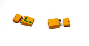
The XT90 connectors with built in precharge are perhaps the easiest solution.
They are called "spark resistant" connectors by some vendors. They have a resistor and staggered connections so the resistor is in the circuit when first plugging it in, then as the connector is more fully joined it bypasses the resistor.
I got some from Lunacycle.
They are called "spark resistant" connectors by some vendors. They have a resistor and staggered connections so the resistor is in the circuit when first plugging it in, then as the connector is more fully joined it bypasses the resistor.
I got some from Lunacycle.
Attachments
Alan B said:The XT90 connectors with built in precharge are perhaps the easiest solution.
They are called "spark resistant" connectors by some vendors. They have a resistor and staggered connections so the resistor is in the circuit when first plugging it in, then as the connector is more fully joined it bypasses the resistor.
I got some from Lunacycle.
Looks awesome!
I thought that the resistor depends on the voltage and such, how come this one is universal?
Alan B
100 GW
The resistor is not critical. It just slows the charging down. The actual charging rate isn't very important.
Just for fun I'll measure one of these Luna ones. They're probably standard, Luna doesn't make them.
These say "Amann XT90-S" on them.
I measure about 5.5 ohms, so this limits the initial current to Voltage/5.5 amps. So on a 60V setup that would be about 10 amps. Without this resistor the current could be many hundreds of amps or even more.
Most folks use more resistance when they make precharge circuits, but it really isn't critical. Charging the capacitor at 10 amps or 1 amp solves the spark problem either way. Even though there still may be a small spark the energy and damage is significantly reduced with the resistor limiting the current.
One issue is the resistor heats up each time the precharge is used, and it might overheat. The heating depends on the capacitor bank energy. If the cap bank is too big the resistor will overheat. Make sure to avoid doing precharging several times in a short period, the resistor needs to cool off and it is internal to the connector. Clearly this small resistor could fail with a large enough capacitor bank.
tjgaryiv60
10 mW
I know this is a old post but I am in the same situation now about how to connect the ignition wire. I have a chinese minimal instructionws
and bad wiring diagram that matches some wires while others are not listed at all. All labels in chinese. It is supposed to be a 72v-120v
24 fet 80 amp controller. I am only hooking up the minimal wires such as phase, hall, throttle, main battery and " SMALL RED WIRE IGNITION
WIRE ". I spliced it directly to the red main positive wire with a bullet quick connect / disconnect connector. I am not an electrical
engineer nor a newbie but I do need advise or comment to make sure I am not doing something wrong. I have not powered the controller up.
I was going to connect hall throttle phase. Then main battery connector ( anderson type battery quick connect / disconnect 6 ga wire /
amp rating not listed ) LAST CONNECTION THE SMALL RED IGNITION WIRE BULLET CONNECTOR. Is this correct or OK.
Then I am going to have to find right phase / hall combo with the wheel lifted at no load and go easy on throttle. I have only done this by trial and error once and I got lucky and it was the 2nd or 3rd wire swap that took me about 5 minutes time.
Just for the info the motor is a Mxus V3 DD rear hub rated either 3000w or 5000w. I will run 2 battery packs parallel 20s 4p 26650 3.7v
5000ma cells to give me 20ah per battery. They have a 40a continuous bms 120a peak. Both of these will be connected in parallel should give
me 72v 40ah and 80a output. Does this sound correct ? It is going on a Fat Tire Bike 4.0 " x 26" tires with air / gas front fork and
rear wheel torque arm.
Thumb throttle and a digital volt meter on handlebar.Please let me Know
Thank you
Voltron
1 MW
That all sounds right.... And fun! The only thing I would say though is get a bar mount switch to run the ignition wire thru.. or make the bullet connector stick it someplace reachable for emergencies like a shorted throttle or something... Guess how I know that's important? 
Similar threads
- Replies
- 2
- Views
- 103
- Replies
- 5
- Views
- 655