Sergiocielo
1 mW
- Joined
- Mar 22, 2017
- Messages
- 15
Dear Member.
I have several questions regarding this motor's sizing that corresponds to PMBLDC Direct Drive chinese production by Mxus, QS motor and Others.
As you know the range of power is 350-5000W but the Pedelec's regulation imposes to limit battery voltage up to 48 VDC.
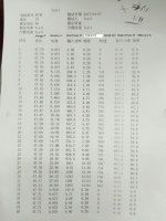
1. one of the available configuration, fine known as I saw discussed in this forum, has stator jacket with 51 slots and rotor annular ferromagnetic steel with thickness 6.5 mm with 46 glued magnets. This is used up to 1000 W nominal power with flat magnets 13.64-30-3 mm /51 Windings (4 turns-15 Parallel-0,53 wire) and for this I have dyno test for unloaded speed of 651.6 rpm with very interesting efficiency. So that I'm interested to improve firstly this configuration or like this with the goal of high efficiency and high temporary torque resistance.
2. the second configuration called V2 and V3 has the same diameters but uses different material and reduced poles to 32 magnets of more sizing.
I saw here several simulations and good competence so my question are:
A. What is the maximum theoretical unloaded speed we can achieve with configuration similar to 1. also acting by controller?
B. what can be suggested to improve efficiency?
Please condider that to increase torque we will use this motor assembled to a reducer having 3:1
Thanks for your suggestions
I have several questions regarding this motor's sizing that corresponds to PMBLDC Direct Drive chinese production by Mxus, QS motor and Others.
As you know the range of power is 350-5000W but the Pedelec's regulation imposes to limit battery voltage up to 48 VDC.
1. one of the available configuration, fine known as I saw discussed in this forum, has stator jacket with 51 slots and rotor annular ferromagnetic steel with thickness 6.5 mm with 46 glued magnets. This is used up to 1000 W nominal power with flat magnets 13.64-30-3 mm /51 Windings (4 turns-15 Parallel-0,53 wire) and for this I have dyno test for unloaded speed of 651.6 rpm with very interesting efficiency. So that I'm interested to improve firstly this configuration or like this with the goal of high efficiency and high temporary torque resistance.
2. the second configuration called V2 and V3 has the same diameters but uses different material and reduced poles to 32 magnets of more sizing.
I saw here several simulations and good competence so my question are:
A. What is the maximum theoretical unloaded speed we can achieve with configuration similar to 1. also acting by controller?
B. what can be suggested to improve efficiency?
Please condider that to increase torque we will use this motor assembled to a reducer having 3:1
Thanks for your suggestions