
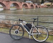
A bit a learning experience I have started working on a controller two years ago. Target is a mostly road legal bike for Europe, i.e. with speed limit, power limit and pedal sensor.
Main features are:
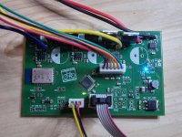
Simplicity and clean layout are key as the main ideas are to have it robust and repairable.
I have done a few revisions already and it is working flawlessly since several thousand kilometers.
Main features are:
48V / 1000W
based on Atmega 328 microcontroller ("Arduino")
block or sinus + eventually sensorless commutation
regenerative braking
60V-> 12V DC/DC converter with 7.2W output, thus around 5W for light or smartphone
bluetooth 4.0
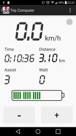
android app for configuration and logging
open hardware and potentially open software
size 60mmx100mm
Simplicity and clean layout are key as the main ideas are to have it robust and repairable.
I have done a few revisions already and it is working flawlessly since several thousand kilometers.
")

