FOC identification

Joined
Jul 7, 2008
Messages
3,963
Location
Missouri
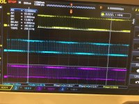
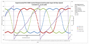
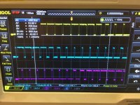
I've been having some lively discussions over a new controller in the RC realm that is claiming closed loop FOC. By all accounts, I can't make it fit what I know to be FOC. Mainly, when looking at the voltage from the controller, it is quite trapezoidal in shape. The area under the curve has a linear rise and fall, and at half throttle spends 1/3 of the time at full duty and 1/3 of the time at 0 duty. There is a 14khz AC waveform on top of the typical commutation, in order to lock in the motor speed to the drive frequency. The motor is a nearly perfect sine bEMF, so the controller output should be close to a sine wave with the typical dips in the middle where reluctance is at min/max. So far, I have quite a few engineers in agreement that this is either a poor attempt at FOC, or not FOC at all. They are using an encoder on the motor, but encoder doesn't = FOC.

What say you? Any more data I can gather short of destroying the controller?
 

Attachments

  • switching grab.jpg
    switching grab.jpg
    138.9 KB · Views: 1,545
  • FOC voltage profile.png
    FOC voltage profile.png
    47 KB · Views: 1,545
a zoomed in look at the switching at 50% throttle. Very linear rise and fall to duty cycle, with very large portions spent at 0 and full duty. Curious.
 

Attachments

  • grabbed frame 2.jpg
    grabbed frame 2.jpg
    138.2 KB · Views: 1,544
Its the typical moving midpoint sinusoidal output... this does not mean its foc just that it is sinus out.

The clou is that each if the waves looks kind of trapezoidal, but the DIFFERENCE between two voltages is sinusoidal (and with a max amplitude larger than what fits in the supply, which is the reason for moving midpoint). The motor only cares about the voltage difference between its terminals.

I do the same in my controller IC.

With your scope, between controller out and scope put a 1 kHz RC lowpass filter. Then use the subtract function to see the sine.
 
They are running a 14khz AC waveform on all three phases, like a stepper driver. Seems to cause currents on the RC filter, smoked the first set :lol: . The bits I have to build a 1k LPF are 10ohm resistors and 10uf caps, I'll need some different values to tamp down the currents I suppose.
 
I differenced two phases without the filter and it’s a square wave. Ground on the negative terminal, probes on the phases.
 
A hobbywing unit. It is only compatible with their motors and offers no tuning of motor parameter, so it's quite limited in this regard.
 
johnrobholmes said:
A hobbywing unit. It is only compatible with their motors and offers no tuning of motor parameter, so it's quite limited in this regard.

Looking at it, it probably is FOC, it won't run other motors as FOC needs to know the motor resistance, inductance and flux linkage. FOC controllers have to either be matched to motors or include motor detection functions.
 
I think it would be hard to tell if it has true FOC just by looking at the output waveform. My cheap sine wave controller is not FOC, but the output looks very similar and it does field weakening.

Can you tell if the controller has phase current measurement (shunt resistors or hall sensors)?
 
It is potted so I can't really get into it without destruction. I have asked the company to reference the type and position of current sensors if they would like to give me some information to go on.
 
Back
Top