Propeller load for setting hall sensor position

larsb

1 MW
Joined
Dec 10, 2014
Messages
2,821
Location
Gothenburg, Sweden
I want to optimise hall sensor position and don't think it's easy to get it perfect:
If you measure current vs hall position at no load/WOT then the hall setting vs current is not very sensitive to position.

I don't have a scope, and they measure voltage so the inductance will mess up the reading as you want the current at the correct time and not the voltage. Correct?

I thought about using a propeller as a simple way to load the motor for hall sensor positioning, like this one:

http://vi.raptor.ebaydesc.com/ws/eBayISAPI.dll?ViewItemDescV4&item=372228986681&category=182204&pm=1&ds=0&t=1530527339886&cspheader=1

It's not so expensive, the load should be constant for other factors than RPM, and a simple measurement of current at WOT or even rpm would give the best position.

What do you think? I've never seen it done with a propeller here at ES.
 
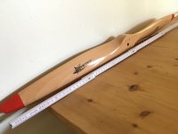
Received propeller today! It's 32 inches/810mm long and should push some air at full throttle :D
image.jpeg
Relly looking forward to this! 8)
I need to fix a propeller adapter to my motor but motor is in transit now, a friend has had it for his DIY controller development.
 
Is that this project?
https://endless-sphere.com/forums/viewtopic.php?f=2&t=30680

It'll be interesting to see how a prop works as a load for this type of testing....
 
Yup, that's where my Revolt motor has been. Results for the incemed controller with my motor are improving, i will try his controller in a while with updated settings. It's great that my bastard motor can contribute.

My own testing is for sensored drive. I have tried to set halls earlier by optimizing noload current without load but the measurement vs position is very unsensitive - i now think it is useless. It probably is better to set halls in neutral position and not optimize it at all if it's done this way.

Come to think of it, both Burties hall module testing and my own fiddling indicate that the noload is insensitive to hall position, and the actual loaded results don't compare to the unloaded.

So my idea is to use the propeller as a simple way of loading motor without introducing new noise factors (or building a dyno :D ).
 
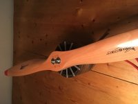
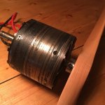
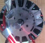
Progress! Made the propeller adapter today. Had to mill out the center hole to 15mm, then screwed it to a double split shaft collar.
image.jpegimage.jpeg

Let's hope it holds, otherwise i'll be the first at ES with severed E-limbs :D

I've got a feeling it would be fun to build a paramotor rig..
 
I have tried the hall setting :D
https://youtu.be/S58HCyYliYs
There's a definite limit in the retarded position. At a current slightly less than 26A the motor just dies. When advancing the position both rpm and current rises so rpm cannot be used for setting an optimal position. That's too bad, i think the load needs to be higher than the propeller with the speed i've got (3400 rpm). I could build a transmission and gear it up 8)

There seem to be a peak in the behaviour, after increasing to a position with 31A consumption the current and rpm starts decreasing slightly. Further advancing of the halls eventually turns the motor into runaway, suddenly current rises to 50-60A and rpms increase significantly.

I wonder if the 31A peak can be the best position?

I need a better test setup with logging :D
And that $$$ oscilloscope.
 
If you had a way to keep the rpm constant while adjusting, you would be able to find the optimal setting easier. You could manually adjust the rpm to a certain value for each measurement then look for the minimum current setting.

You can find neutral position by applying a DC current to pairs of phase wires and letting the rotor move. The current needs to be enough to lock the rotor in position but not so much that it gets really hot. Swapping pairs of phase wires will align a different sensor. With DC applied, the neutral position for the sensor will be right where it toggles. You would have to try different combinations to figure out which sensor is aligned for a given pair of phase wires.
 
fechter said:
You can find neutral position by applying a DC current to pairs of phase wires and letting the rotor move.

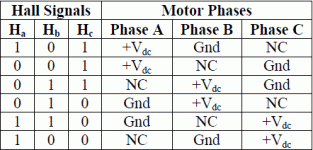
That's a really good suggestion! I did the same for setting the RLS sensor i used before following a commutation table:
image.gif

I can compare the position i have set now to the neutral energized coil position. That'll give a good reference but not necessarily the answer what's the best setting :D
 
Propeller set hall position, noload 5.8A, propeller WOT current 31A.
image.jpeg

Phase activation hall position, noload 5.5A, propeller WOT current 27.6A @ 3250 rpm
image.jpeg

The propeller setting is close to the phase activated (neutral) position. It took some effort to set/find and i don't think the neighbours loved the propeller music 8)
It is a bit advanced from the neutral phase activation position, roughly 30 electric degrees judging from the pictures.

I'll do a test drive with the phase activated setting and see if i notice any difference in performance compared to the location i had before.

By the way: I really like this little bugger, makes life easier :D
 
I did a test with the sensorless controller:
Noload 4.7A @ 3250 rpm
Propeller current 26A @3160rpm
https://youtu.be/nKjm76MYnvY

The hall sensor controller is currently more effective at load even if the noload current is better for the sensorless.. That was a surprise!
 
larsb said:
I did a test with a sensorless controller:
Noload 4.7A @ 3250 rpm
Propeller current 26A @3160rpm

The hall sensor controller is currently more effective at load even if the noload current is better for the sensorless.. That was a surprise!
FWIW, though we're still in the tuning process, this is true (at low speeds at least) of the generic sensored Grinfineon 12FET vs the SFOC5 on my MXUS hubmotor, too.

I expect it has to do with whatever algorithm the sensorless uses to do position determination, and how well tuned it is to the motor. But I don't know enough about how all of that works to say for sure. :/
 
safe conclusion from this test was that it's not a success.
It was meant as a simple way to set optimal hall sensor position without using an oscilloscope but it did not bring any extra value other than the fun of pretending to be an airplane for a while :D

If i'd had a potentiometer to throttle to set the exact same rotation speed after the hall adjustment then it could have given some good data on what was the best position.

It was fun anyhow..
 
Back
Top