Motenergy 3031001 40kw axial motor

ElectricGod

10 MW
Joined
Nov 1, 2015
Messages
3,404
Location
3 OH 3
What is this motor? All I know is it's PMAC. Looking at pictures of a Motenergy ME-1202 like found here, is pretty convincing that is what I have, but then that motor is rated for 10kw and 24kw peak. Considering how beefy this motor is, I'm highly doubtful that 40kw is high enough.

https://www.electricmotorsport.com/me1202-brushless-motor-24-72v-5000rpm-10-kw-cont-24-kw-pk.html

What I know is that it is PMAC, has dual stators and the phase wires are 4 awg. The motor is approximately 9" x 9" and weighs a lot, but I don't have a scale to know for sure. Nothing about this seems to match up with "!0kw continuous and 36 pounds" for the ME-1202. This Is thebig brother to the ME-1202. I know Greentech is no longer in business and I can't find any documentation on this 3031001 motor right now. The motor shaft is at least 3/4" across. For 10kw, a 12mm shaft is sufficient. Why so much beefiness in this motor if it's a measly 10kw?

Motor%20name%20plate.png

P1020432.jpg

P1020433.jpg

P1020434.jpg

P1020436.jpg

P1020437.jpg

P1020438.jpg


For comparison, here's an Alien Power 12090 outrunner. AP rates them for 18kw. How can this giant PMAC be 10kw? This thing is 6 or 8X larger than the 12090. Look at how big it is next to my size 13 shoe!

P1020428.jpg

PMAC%20vs%2012090%202.jpg

P1020430.jpg

P1020431.jpg
 
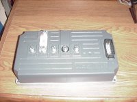
This is the matching controller.

MVC-009F.JPG

80v 500a fuse.
I have lots more if you can get these to run.
 
Weighed a motor. 43lb
It could be the same frame size as the me-1202.
With more copper?
 
43 pounds...hmm... the ME-1202 supposedly weighs 39 pounds. I'm thinking this must be the big brother. That could be accounted for in more copper. 4 pounds is a good bit of copper!

4 awg phase wires to each of the 6 phases..that indicates insane amounts of phase amps!
 
Inwo said:
This is the matching controller.

MVC-009F.JPG

80v 500a fuse.
I have lots more if you can get these to run.

Send one along when you get the chance. I can at least take it apart and look at the inards to get a good idea of what it really delivers to the phases.

I'm assuming 500 battery amps max. AT 80 volts, that works out to 40kw into the controller and something a good bit more into motor. That fits right in with what I've been saying about this motor not being a 10kw motor like the ME-1202 specs claim. I'm thinking 50 or 60kw continuous the more I think about things.

I REALLY want to take it apart this weekend to see how big the magnets and stators really are. I think the walls on the cast shell are 1/4" thick pretty much everywhere. Since the motor is 9" across then that means the stator and rotor are probably about 8.5" across. The motor housing minus the mounting end and the protrusion for the position sensor leaves about 7". Subtract 1/2" from that for shell wall thickness leaves about 6.5 inches internally for 2 stators and a rotor. It looks like the stator I can see is about 1.75" thick or 3.5" of total stator thickness. That leaves approximately 2.5" of thickness for the rotor. That makes for a LOT of iron, copper and magnet mass! How that equates to 10kw is a total mystery to me and is yet another hint at the motors real power being something like 50-60kw.

THere's just zip for documentation on this motor that I have found. I'd really like to know a lot more about it!!!
 
I contacted Greentech when I was buying distressed merchandise from them. They claim that the the main company is still in business pursuing other projects.
Greentech executives may have access to paperwork and files.
 
Inwo said:
I contacted Greentech when I was buying distressed merchandise from them. They claim that the the main company is still in business pursuing other projects.
Greentech executives may have access to paperwork and files.

The box the motor was in says Motenergy on it so I have contacted them about the motor. Are you pursuing this Greentech avenue for information?
 
It's a cool looking motor and the true continuous rating probably is around 10KW when tested according to the ISO standard (or similar). It will be intended to tucked away under a vehicle, with minimum airflow and to lug it around all day under all likely conditions for years on end without failure. Peak power probably is the 50-60kW you estimate, maybe more for a few seconds burst on a cold motor.

By contrast the Alien Power motor rating is the typical RC joke. You can't really compare the two :D
 
It looks like maybe axial flux, since the windings are showing near the shaft and you have two stators. It may be very difficult to take apart due to magnetic force.

That's a big one for sure. You could make your own version of DeathBike. Making the controller work without documentation or programming software might be a challenge.
 
fechter said:
It looks like maybe axial flux, since the windings are showing near the shaft and you have two stators. It may be very difficult to take apart due to magnetic force.

That's a big one for sure. You could make your own version of DeathBike. Making the controller work without documentation or programming software might be a challenge.

Yes...dual stator axial motor.

I have gear pullers in various sizes. I do take apart motors from time to time and anything size 60 outrunner or above gets pulled, not torn apart by hand. Going back together is done with the puller as well. The last thing I want to do is lose control and slam magnets into the stator and break things. I'm pretty confident that one of my pullers will do the job.

PMAC and BLDC are essentially the same except for how position is detected. I'll add a set of halls to each stator. Then I'll separate the stators so I can run on dual BLDC controllers. I may need to make or mod controllers for this. I have a 24 fet controller and I think I can run it at about 20kw max at the motor. 2 of them ought to get me in the low end continuous ball park of what I can expect out of this motor.

Deathbike...a friend of mine loves the Honda Ruckus. His personal Ruckus has a 232cc engine kit on it. That gets him something like 25hp. He has a spare Ruckus that is just sitting in parts right now and we are talking about dropping this motor on it. We would more than double the horse power that he currently has with the biggest gas engine he can fit on his Ruckus. I think that would categorically make it into a death Ruckus! Who knows what other implications would arise from this much power. Honda designed the Ruckus around 50-150cc power. AT 232cc he has to reinforce quite a few things to keep it from snapping in half. I'm thinking that the entire back end of the Ruckus will literally tear off at full power without a lot of reinforcing. Will it be as fast as something like a Hyabusa? God! I sure hope so!
 
Punx0r said:
It's a cool looking motor and the true continuous rating probably is around 10KW when tested according to the ISO standard (or similar). It will be intended to tucked away under a vehicle, with minimum airflow and to lug it around all day under all likely conditions for years on end without failure. Peak power probably is the 50-60kW you estimate, maybe more for a few seconds burst on a cold motor.

By contrast the Alien Power motor rating is the typical RC joke. You can't really compare the two :D

You are absolutely correct about AP over rating their motors. This is a well known fact. I have a C80100. AP rates it at 7kw. Uhhh no not likely, but I know I get something like 4.5kw continuous out of it. Probably a 12090 is more like 10-12kw continuous, NOT 18kw.

10kw continuous out of this motor...that's soooooo way below what it is really going to deliver continuous. I will be opening it up and I want to use forced air ventilation. I think a radial fan some where on the shaft will do the job nicely. Maybe mount an EDF to it?

I did this with an HLD inrunner some time back and it purrs along at well over 5kw continuous and never warms up. All while hauling around doing 50-60mph.

Motor%20bracket%204_zpsoxcbpazx.jpg

Motor%20bracket%205_zps8zyjteas.jpg


This 3031001 makes that HLD inrunner look like a tennis ball by comparison. Ventilating it and using forced air...40kw continuous wont be difficult to maintain. Maybe 50-60kw will be peak. I'm willing to find out it is. :):):):):)

Intended use...LOL...how does that have anything to do with DIY? A razor is intended to shave your face, but run a thin wire across it and you have a radio tuner. Just about all my EV's have repurposed brass plumbing parts in them. An old knife makes a great device for getting into narrow cracks. The tiny gap between a motor bell top and the magnet cylinder is too small to get a screw driver in there, but a sharp knife edge will go in if you tap on the back of the blade. An appropriate diameter socket is perfect for driving in a bearing into a wheel hub. "Intended use" just means someone hasn't thought about all their options yet.

Do you know anything about these motors or did you just read the online specs for the ME-1202? The specs and what I hold in my hands...well they don't jive!
 
The information from Them is that it's the me-1202 with another set of parallel windings.
I have the files for the 1202.
Could that be used as a starting point, or would I need to disconnect the added copper?
Also have unverified files for 3031. They load with errors. 😣
 
I got this back from Motenergy...

Max amps is 450 amps for 2 minutes.

120 amps continuous,

4000 rpm at 72 VDC = 55.55 Kv

Y connected.

4 pole pairs.

Up to 96 VDC.

So then, these numbers HAVE to be really conservative! 96v at 120 amps is a measly 11,500 watts. and 450 amps (peak for 2 minutes) at 96 volts is 43kw. I'm still skeptical that those are real numbers. I'm betting I can do far better than 11kw continuous without issues.
 
This motor is an NOT an ME-1202, but rather an 3031001. With the larger stator and probably larger magnets, that accounts for the 43 pounds instead of 39 pounds.

I got a PDF in the mail a little while ago. Here is the whole thing and close-ups of important sections.

31001-AE%20Drawing.png

31001-AE%20Drawing%20-%20upper%20left.png

31001-AE%20Drawing%20-%20center.png

31001-AE%20Drawing%20-%20Upper%20right.png

31001-AE%20Drawing%20-%20encoder%20info.png

31001-AE%20Drawing%20-%20notes.png
 
Some more stuff on this motor. If you need bigger pics of this stuff, jsut post up and I can expand out sections of the PDF's as needed.

Armature dimensions and construction...I can totally replace the shaft! It's already keyed too. I need to drive out the factory shaft and insert a new one. Easy peasy! After that mounting a front bearing will also NOT be hard.

3031001%20armature%20drawing%201.png

3031001%20armature%20drawing%202.png


How many motors actually have dyno sheets for them from the factory?

3031001-Dyno%20Plot.png
 
I've had this motor a matter of days and have wanted to take it apart. I finally had time to do that tonight.

Everything that comes apart has an o-ring under it. The 2 halves of the motor shell seal together with an o-ring.

On the back of the motor, there's an o-ring sealed end cap that has the optical position sensor and temp sensor under it.

3031-001%20position%20encoder.jpg


I think sometimes the 2 stators don't line up exactly so these elongated bolt holes allow for what looks like 3 or 5 degrees of rotation. My motor has spring pins in the second holes so I guess this motor doesn't need alignment.

3031-001%20stator%20alignment.jpg


Getting these 4 awg wires off the brass bolts was not exactly easy. They are short and quite stiff.

3031-001%206%20phases.jpg


This is the completely wrong way to use a puller, but I had a nice ledge inside the top shell to grab onto and the motor shaft was perfect for pushing against. I had to keep the puller jaws from retracting inwards. Wedging them outwards against the shaft with some M10 bolts worked pretty well. Later I used 3 pocket screw drivers becasue they have a slightly larger diameter.

3031-001%20pulling%20the%20top%20stator.jpg


A couple pics of the top stator. It's pretty close to 2" thick and 7" across. The windings are a bit loose in places, but it's all soaked in epoxy. Each strand looks to be 14 awg.

3031-001%20top%20stator.jpg

3031-001%20top%20stator%202.jpg


The armature is made of 8 magnets that are about 3/8" thick and 1.75" across. The outer diameter of the magnets is just short of 6" across. I don't know what N rating they are, but they are VERY strong! DON"T get anything steel close to the magnets. It will get pulled in faster than you can react. The magnets are held in place in the aluminum carrier by a steel frame around them that traps the magnets and holds them in place in the carrier. The magnets and the carrier measure 20-30 milliohms between them.

3031-001%20armature%201.jpg

3031-001%20armature%202.jpg

3031-001%20magnet%20close-up.jpg


I'm not sure how I'll pull the armature off the bottom stator. The magnets are insanely strong! I'll have to figure it out so I can pull the shaft and replace it with a longer one keyed it's entire length for chain drive. The shaft is .94" or 23.87 mm according to my micrometer. The armature drawing says .90". The armature key is 6mm.

3031-001%20motor%20shaft%20close-up.jpg
 
Thanks for posting the teardown pics. That's pretty interesting. I've never seen magnets held in by carriers like that. Seems like there would be a better way to do that. That thing has some pretty serious copper.
 
EDF's or Electric Ducted Fans are super cheap and readily available from any RC outlet such as HobbyKing. A 40mm EDF produces a LOT of air flow. Inside the motor shell is a lot of empty space that isn't doing anything. The motor could have been designed differently and be trimmed down to take away the 12mm wide gap around the stators. I look at this and see opportunity for lots of air flow. Over watting will be one of my primary goals when I use the motor. It was intended to sit in a dead air space on a differential. I intend for it to be in open air and used hard. Forced air cooling will be needed. Heat conduction currently happens via the section of the stator that bolts to the ends if the motor shelsl and then radiates passively via the external fins on the shell.

This is the top stator. The air gap around the armature is about 1mm and the rest of the air gaps are about 12mm. There's lots of space for good air flow around the stators here.

3031-001%20top%20stator.jpg


Same for the bottom stator.

3031-001%20armature%202.jpg
 
fechter said:
Thanks for posting the teardown pics. That's pretty interesting. I've never seen magnets held in by carriers like that. Seems like there would be a better way to do that. That thing has some pretty serious copper.

I thought the carriers were odd too. Maybe someone was concerned that an epoxy would fail? It does make swapping out a magnet pretty easy. Bend up those 6 tabs, pull the magnet. The fit between the magnet, carrier and armature disk is an interference fit. The magnets do NOT move at all once installed.

Serious copper...do you think 60kw is tenable or am I fantasizing? I really don't know. I have no experience with a motor this big. I'm flat out guessing what its potential really is.
 
Hey ElectricGod, really great teardown with lots information.

I got this same motor and was wondering what specs and stuff it has. you mentioned you had a PDF available but now the photos seem to have been deleted. is there any chance you can repost the PDF and teardown pics? Thank you 😊.
 
EG had a hissy fit some years back and deleted his stuff, then did things that required banning to stop him, so he's not around here anymore. (he's tried to come back more than once, and treated people...unkindly... so has not been let back in (and wont' be)).
 
Back
Top