Mora
100 µW
Hello,
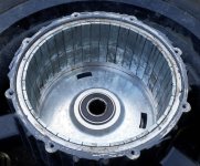
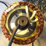
I have a electric scooter which I've been riding for a year now. It was sold here as "Leone Ecopower" and I think it is/was sold as "Evader" elsewhere. I bought it used and previous owner had replaced its original controller. It was obviously some cheap chinese controller but so was the replacement. It gave jerky starts and some electrical noise coming from motor. I got myself a Phaserunner controller from eBikes.ca. It doesn't want to tune to this motor properly and throws me hall sensor errors. I can run it sensorless but would love to get it working sensored. Tried swapping hall sensor order while phase leads were left untouched. This did lead me opening the motor and inspecting insides. Too bad I cannot fully identify the motor type as text on it has partially worn out. I thought I would post pictures and questions here if somebody else happens to have similar motor.
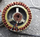
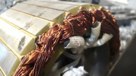
It has 40 magnets around the rotor and stator has 36 teeth. I have no idea about actual winding scheme but it looks like three stator teeth are wound as one magnetic pole, wire skips next 6 slots and there is another pole starting from there. It looks delta wound as I see no wye (star) point.
It goes like this (imo): phase A slots:
1 2 3 4 5 6 7 8 9 10 11 12 13 14 15 16 17 18 19 20 21 22 23 24 25 26 27 28 29 30 31 32 33 34 35 36
I've read various hall effect related threads here for days. Does winding pattern matter in this situation or is it only magnet position related thing? I read that delta windings might offset timing by 30 degrees.
360 degrees / 36 teeth = 10 degrees mechanical for every tooth. So halls are spaced 15 degrees mechanical apart from each other.
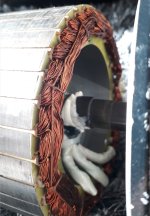
360 degrees / 20 magnet poles = 18 electrical degrees per one full mechanical rotation. Hall sensors should be placed 120 electrical degrees apart from each other, right? How come 3 hall sensors are spaced like in pictures (every 1.5 teeth or 2nd sensor in slot and two other embedded to stator teeth)? Should I re-arrange hall sensors?
Now I've seen similar hub motors with similar hall spacing. They seem to work. I got a 3000W MXUS motor with hall sensors that works fine with Phaserunner. It tunes properly and works in fully sensored mode. Pulls nicely from standstill even with a 120kg rider (80 phase amps, pack at 48V). Even this Evader motor pulls okay from standstill when using cheap chinese controllers.
I've ordered new hall sensors already (Honeywell SS41G) and some thicker and more flexible phase wire (12AWG).
Main question is: should I alter hall setup? If not, are current hall positions 120 electrical degrees apart from each other?
Thank you for all the help.
I have a electric scooter which I've been riding for a year now. It was sold here as "Leone Ecopower" and I think it is/was sold as "Evader" elsewhere. I bought it used and previous owner had replaced its original controller. It was obviously some cheap chinese controller but so was the replacement. It gave jerky starts and some electrical noise coming from motor. I got myself a Phaserunner controller from eBikes.ca. It doesn't want to tune to this motor properly and throws me hall sensor errors. I can run it sensorless but would love to get it working sensored. Tried swapping hall sensor order while phase leads were left untouched. This did lead me opening the motor and inspecting insides. Too bad I cannot fully identify the motor type as text on it has partially worn out. I thought I would post pictures and questions here if somebody else happens to have similar motor.
It has 40 magnets around the rotor and stator has 36 teeth. I have no idea about actual winding scheme but it looks like three stator teeth are wound as one magnetic pole, wire skips next 6 slots and there is another pole starting from there. It looks delta wound as I see no wye (star) point.
It goes like this (imo): phase A slots:
1 2 3 4 5 6 7 8 9 10 11 12 13 14 15 16 17 18 19 20 21 22 23 24 25 26 27 28 29 30 31 32 33 34 35 36
I've read various hall effect related threads here for days. Does winding pattern matter in this situation or is it only magnet position related thing? I read that delta windings might offset timing by 30 degrees.
360 degrees / 36 teeth = 10 degrees mechanical for every tooth. So halls are spaced 15 degrees mechanical apart from each other.
360 degrees / 20 magnet poles = 18 electrical degrees per one full mechanical rotation. Hall sensors should be placed 120 electrical degrees apart from each other, right? How come 3 hall sensors are spaced like in pictures (every 1.5 teeth or 2nd sensor in slot and two other embedded to stator teeth)? Should I re-arrange hall sensors?
Now I've seen similar hub motors with similar hall spacing. They seem to work. I got a 3000W MXUS motor with hall sensors that works fine with Phaserunner. It tunes properly and works in fully sensored mode. Pulls nicely from standstill even with a 120kg rider (80 phase amps, pack at 48V). Even this Evader motor pulls okay from standstill when using cheap chinese controllers.
I've ordered new hall sensors already (Honeywell SS41G) and some thicker and more flexible phase wire (12AWG).
Main question is: should I alter hall setup? If not, are current hall positions 120 electrical degrees apart from each other?
Thank you for all the help.