How much Heat can To-247 handle in real world

ElectronS

10 mW
Joined
Mar 4, 2013
Messages
31
Hi guys i am a newbie EE building a 2 parallel mosfet per side power stage , and would like to know how much current is possible to pass for 2 minutes (peak) and 60mins continous. by figuring out how much thermal power a to-247 package can handle from your experience .

The power stage will be something like this :
fJmUTe

kart173.jpg

except that the bottum plate attacked to the U shaped heat spreader will be finned 20x20cm heatsink with a 20-to 30CFM fan

The mosfet RDsOn is 2mohm (Tjunction max is 175 , though i would like to stay way below this number maybe 125degree max)
the thermal resistance from jucntion to heatsink (jun-to case + case to heatspreader + heatspreader-to heatsink ) is approximatley 5 degree C/W .

is 16w (~200A)a realistic number for 2mins peak ?
is 10w (~150A)a realistic number for 60mins continuous ?

EDIT: ADD more details

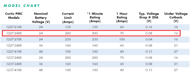
For example curtis 1227-2402 controller (which is a very similar controller to one in the picture) is rated for 200A (1-2 minutes) and 70A for 1 hour
222.png
it uses 5 mosfets in parallel per side ( x4 sides because it is an H bridge ) , mosfet is IRF3205 , the mosfets are connected to the aluminum block using grease only (to share current maybe) and the aluminum block then it is insulated from the buttom plate using silicon pad
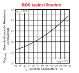
111.png
assume the mosfet is at 100degree max , the resistance will be 1.5x8mOhm = 12mOhm , at 200A , each mosfet will be conducting 40A , then Ploss per mosfet is 40x40x12/1000= 19.2W !!!!
I thought this number was crazy for to-220 , Thats why i asked my question about the to-247.
 
What does the RDSon go up to at those temperatures?

The resistance goes up with temperature, which generates more heat, which raises the temperature....so you have to account for that, too.

Also, I'd recommend assuming worst-case thermal resistances between all the parts and heatsinks/etc., just in case.
 
ElectronS said:
Hi guys i am a newbie EE building a 2 parallel mosfet per side power stage , and would like to know how much current is possible to pass for 2 minutes (peak) and 60mins continous. by figuring out how much thermal power a to-247 package can handle from your experience .

The power stage will be something like this :
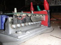
Those are TO-220's not TO-247's.

To figure out max temp you need two things:

1) Heat. For static loads it's easy; it is I2R where R is RdsON. For switching loads it is a lot harder, since you have dynamic losses as well, and these depend on a great many things (like Miller capacitance, which changes with voltage.)

2) Theta J-A (thermal resistance, junction to ambient.) FETs come with two ratings - theta JA and theta JC. Theta JA is what you get with no heatsink. Theta JC is the resistance between the junction and the case. You then add the additional resistance of the heatsink's theta CA (case to ambient) to get the total thermal resistance. Once you know those two things you can calculate the max temp you will see above ambient.

Finding a heatsink's theta CA is difficult, but in general the more surface area, and the more airflow, the lower the resistance.
 
amberwolf said:
What does the RDSon go up to at those temperatures?

The resistance goes up with temperature, which generates more heat, which raises the temperature....so you have to account for that, too.

Also, I'd recommend assuming worst-case thermal resistances between all the parts and heatsinks/etc., just in case.

yes i looked at the datasheet rds vs tempreture
The mosfets i will be using are :
IRF100P219 (2.5mohm at 12v vgs at 125degree Qgmax =270nC )
OR IRF100P218 (1.8mohm at 12v vgs at 125degree but Qgmax=555nC)
 
billvon said:
Those are TO-220's not TO-247's.

To figure out max temp you need two things:

1) Heat. For static loads it's easy; it is I2R where R is RdsON. For switching loads it is a lot harder, since you have dynamic losses as well, and these depend on a great many things (like Miller capacitance, which changes with voltage.)

2) Theta J-A (thermal resistance, junction to ambient.) FETs come with two ratings - theta JA and theta JC. Theta JA is what you get with no heatsink. Theta JC is the resistance between the junction and the case. You then add the additional resistance of the heatsink's theta CA (case to ambient) to get the total thermal resistance. Once you know those two things you can calculate the max temp you will see above ambient.

Finding a heatsink's theta CA is difficult, but in general the more surface area, and the more airflow, the lower the resistance.

The picture is for to-220 , but i will be using to-247 , but with similar mounting ( using silicon pad and mosfet clip )

1-I thought that in mosfets switched at reasonable frequencies 16-20khz , the conduction losses (i2R) are the dominant and switching losses can be ignored .

2- That's exactly how i approximated the thermal resistance :
Rjc (to247 datasheet) = 0.44°C/W
R(to-220 silicon pad at 50psi Bergquist company SP-2000) = 2°C/W
R( aluminum spreader to heatsink + heatsink to Air ) i approximated to be 2.5 °C/W ..
Total =5 °C/W
 
Electron, I'm an ol' guy now...and have forgotten the specifics of this calculation I did back in 2012. There should be a thread on here with a deeper discussion. Note the significance of switching losses versus conduction losses at high PWM frequencies.
 
ElectronS said:
1-I thought that in mosfets switched at reasonable frequencies 16-20khz , the conduction losses (i2R) are the dominant and switching losses can be ignored .
Depends on the application.

Low voltage, purely resistive load? That is likely the case.
High voltage, inductive load? You're going to see a lot of heating come from the switching of the FET.

You have to do the math to figure out how much.

Total =5 °C/W
Great. You can validate that number by getting a FET, mounting it to the heatsink, putting X watts in it (for example, by forward biasing the internal diode) and measuring the temperature rise.
 
Why does the table above show FET leg losses decreasing with increased duty cycle? I would have assumed the opposite: more time on, passing 200A = more leg heating = greater resistance = more heating?
 
bigmoose said:
Electron, I'm an ol' guy now...and have forgotten the specifics of this calculation I did back in 2012. There should be a thread on here with a deeper discussion. Note the significance of switching losses versus conduction losses at high PWM frequencies.

Thank u all , you have opened my eyes on the switching power losses , now after 2 days of research i have found an app note from fairchild (now ON semi) called AN-6005 that explains the switching losses in buck converters , i used their formulas to develop my own calculator, hopefully it is accurate and someone else might benefit from it , i will attach here the xlsx file.

View attachment Mosfet power loss calculator.xlsx

in this calculator the formulas used are from "AND9083" , but Qsw estimation to Qsw=Qgd+ Qgs/2 , is from AN-6005 . Hopefully this is accurate , i am still trying to find out what is Qsync ( Qgtotal-Qgd) which is given in datasheets and wether or not should i use it instead of Qsw ??!!
 
One thing to be aware of is much of the time TO-247 are limited by the wirebond to the source pin, it's not uncommon to see 200A+ mosfets dies in TO packages with a 100A limit on the wirebond. You have to check the data sheet for any mention of package limitations.
 
lizardmech said:
One thing to be aware of is much of the time TO-247 are limited by the wirebond to the source pin, it's not uncommon to see 200A+ mosfets dies in TO packages with a 100A limit on the wirebond. You have to check the data sheet for any mention of package limitations.

old to-247 packages like IRFP3077 where limited to 120A , However newer mosfets like IRFP7718 using same to-247 package can handle 195A .. maybe they have modified something internally to increase this number

So i am sure this will not be the limiting factor , right now it is Heat generated (50/50) conduction and switching losses
 
Back
Top