Controlling DC Motor Controller's throttle from vehicle's OBD2 CAN-BUS pins

tallatghazi

10 µW
Joined
Oct 10, 2018
Messages
5
Hi,
Following question is related to DC Motor Speed & Torque Controller's CAN-BUS Throttle input:

I want to operate Curtis DC Motor Controller's throttle via CAN-BUS (Curtis already support CAN input for throttling). In this regarding, I would like your confirmation that can we directly control DC Motor Controller's throttle from vehicle's OBD2 CAN-BUS pins (check attached image)?

TARGET: My target is to run a DC Brushless/Brushed Motor on 100% same RPM as of Vehicle's Engine RPM (on all different loads)
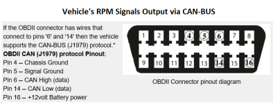
OBD2.png

Thanks!
 
To know for certain, you'd have to check with teh controller manufacturer, to see if the throttle commands from the vehicle are the same as the throttle commands the controller requires, and that they both operate on the same scale.

Even if it is, however, it doesn't mean you'd get the same motor speed out of it, just that the throttle values fed to both will be the same. At a guess, you would have to externally process the CAN data in realtime to cause the electric motor to respond the same as the ICE.
 
I am basically a mechanical engineer and so bit confused regarding electronics side. So allow me to compile all my thoughts and concerns here. Hope you can clear following few points:

TARGET: My ultimate target is to run a DC Brushed or Brush-less Motor on 100% same RPM (WITHOUT ANY DELAY) as of Vehicle's Engine RPM (on engine's different loads)

1- Either I can take running Engine's RPM from a Tachometer with RS232 out put or Tachometer with CAN signals out put (which I have not found yet) or with Crank shaft sensor's output voltage. If you have better suggestion then please share.

2- You are saying that I should not be worried about the SPEED/RPM rather I should be more concerned about LOAD/TORQUE of the engine. As far as your this point is concerned the Curtis 1244 DC Motor Controller already handles RPM/SPEED as well as LOAD/TORQUE of the motor. So, do I still need to be worried about syncing LOAD/TORQUE of the Engine with the motor?
if YES, then exactly HOW and with WHICH electronic device I can instruct DC Motor Controller regarding engine's LOAD.

3- If you would be in my place and to achieve above required TARGET, what would be your exact approach?

MY APPROACH (based on current studies, may be it still requires a lot of further input):
1- Detect engine's RPM via Tachometer with RS232 output.
2- Build a RS232 to CAN signal converter (eventually this conversion kit may cause a very little delay in communication (forwarding LIVE RPM value to DC motor controller).
3- RS232 to CAN signals converter will give CAN signals to the DC motor controller.
4- DC motor controller will run the motor on required RPM and LOAD

Thanks
 
I tried, it doesn't work. The refresh rate of the OBD2's I tested are painfully slow, only a few throttle queries per second, at first glance it sounds like enough, but it is not.
Also during warmup the throttle is a bit more open than usual and the fact it never reaches zero makes it more challenging to get it working.
You want accel pedal feedback with much higher sample rate. It can be done, probably not with OBD.
 
marcos said:
I tried, it doesn't work. The refresh rate of the OBD2's I tested are painfully slow, only a few throttle queries per second, at first glance it sounds like enough, but it is not.
Also during warmup the throttle is a bit more open than usual and the fact it never reaches zero makes it more challenging to get it working.
You want accel pedal feedback with much higher sample rate. It can be done, probably not with OBD.

Sir, in my final conclusion, I am not using OBD anymore, in fact in my point number-1 I have mentioned "Either I can take running Engine's RPM from a Tachometer with RS232 out put or Tachometer with CAN signals out put (which I have not found yet) or with Crank shaft sensor's output voltage. If you have better suggestion then please share."

So please advise as mentioned scenario...
I shall be really grateful.

Thanks
 
If the controller is set to run at a fixed current, it will speed up until it reaches that current. This will automatically be at the same speed as the load over a wide speed range. Changing the current limit changes the torque.
 
fechter said:
If the controller is set to run at a fixed current, it will speed up until it reaches that current. This will automatically be at the same speed as the load over a wide speed range. Changing the current limit changes the torque.

We don't know how Curtis DC motor/Torque Controller is acrually controlling the Speed/RPM of the DC motor?
Do how we can set a constant current to controller?
We can only give different RPMs value inputs to the controller.
Moreover I am unable to understand your this statement "This will automatically be at the same speed as the load over a wide speed range",
Kindly explain...
Please also tell me your conclusions about my required TARGET issue?
 
If the controller has a "torque mode" then the motor will speed up until it the desired torque is made. This is done by measuring the phase current. If the motor has no load, the speed will increase to the maximum possible for that voltage. As long as the engine RPM is below the maximum electric motor rpm, the motor will contribute torque.

To try to put it another way:
Assume the engine and motor are connected by some kind of drive train. Run the engine at a fixed rpm. Increase the motor RPM. The motor will draw close to zero current until it's speed matches the engine, then it will start to climb quickly. This still happens even if the motor and engine shafts are connected. By watching the electric motor current, you can tell how much torque it is adding.
 
fechter said:
If the controller has a "torque mode" then the motor will speed up until it the desired torque is made. This is done by measuring the phase current. If the motor has no load, the speed will increase to the maximum possible for that voltage. As long as the engine RPM is below the maximum electric motor rpm, the motor will contribute torque.

To try to put it another way:
Assume the engine and motor are connected by some kind of drive train. Run the engine at a fixed rpm. Increase the motor RPM. The motor will draw close to zero current until it's speed matches the engine, then it will start to climb quickly. This still happens even if the motor and engine shafts are connected. By watching the electric motor current, you can tell how much torque it is adding.

1- Can you please elaborate that How Controller will detect the Engine's current torque (so that it can instruct the motor to achieve the required torque)?
2- Can you please explain how exactly this will be done "This is done by measuring the phase current" ?
3- Motor and Engine will be connected via thick rubber belt. If at anytime Motor's RPM will be increased as compare to the Engine's RPM then don't you think so that the Motor will slip the belt continuously until Motor & Engine RPM will become the same?
4- Ultimate target is that MOTOR SHOULD SHARE ENGINE"S LOAD (WHICH IS CONTINUOUSLY CHANGING) by syncing RPM.
 
I'm sort of running out of ways to try to explain this.

If the electric motor is driven by a constant phase current (regulated by the controller), the output torque will be constant, regardless of RPM until the maximum motor RPM is reached. The motor will speed up until the current reaches the set point, then it will stay there.

Trying to regulate the RPM and ignoring the current will be very difficult to get a stable output power.
 
Back
Top