Continue EV project or not? Need feedback

halcyon_m

10 W
Joined
Aug 23, 2010
Messages
73
Hi EP,

I started an electric conversion on my 2000 Porsche 911 about 18 months ago and I'm wondering whether to continue it, or not. This decision ultimately comes down to how useful the result will be for others, particularly those on this list that are hobbyists like me. Allow me to explain further:

I am a fan of electric-drive vehicles, whether hybrid, or electric, and I'm also somewhat cheap when it comes to things I can do myself. Last year, I completed my Electrical Engineering Ph.D. at University of Wisconsin - Madison, in what is arguably the best motors and drives program in the world and I definitely feel capable of pulling off this project, but work and other life activities have pulled me away from prioritizing this conversion project.

The conversion project plan was as follows:
1) remove blown engine and transmission, (sell transmission, part engine)
2) Install twin Toyota Highlander hybrid motors from two transmissions along with custom gearing/chain/sprocket to two rear wheels independently
3) Install 650V, 12kWh lithium polymer battery pack (leveraging my dealer account on HobbyKing) and CUSTOM battery management system (Active balancing and monitoring)
4) Install CUSTOM dual AC motor controller with resolver position feedback, 'black box' functionality and a few other general purpose inputs and outputs (fan control, oil pump, etc.)
5) hook it all up, debug the program, test failsafes, and then drive it.
6) eventually hook up a range-extending generator for more than 30 mile range.

As indicated above, this involved two custom projects, a BMS and a drive/controller. Personally, I think the idea of both of these is very cool as a hobbyist and I think (hope) some of you all do as well, but I need to hear this so that I know that if I get both of these custom projects together that someone beyond me could make use of them. The BMS project is further along (tested prototype, see madpowerlab.com for details) than the drive, which is sitting as an un-assembled circuit board and box of components. Like I said, I think these are cool projects and I'd like to see them live, but if it's just for me, I'm not sure I'll find the motivation to complete them.

Secondarily, if there is anyone local to the bay area that would like to lend a hand, that would be awesome. For some more background, I've included a list of specs for each below:

Controller:
dual 3-phase AC motor controller, uses semikron 150A, 1200V modules
Full galvanic or optical isolated gate drivers
Integrated 12V, 600W DC-DC converter fed from high voltage battery pack (650V nominal, but adjustable with design changes)
5 12V switched outputs for accessories
'black box' with accelerometer, rate gyro, and SD card (to record events if they occur, were an event could be a software fault or an actual vehicle crash)
State of completion:
Prototype design complete, hardware on hand, just need to put it together and test it.

Active Battery Management System (LiFe or LiPo):
8 Cell stackable slave boards
9 Cell master board with bluetooth or isolated data output
8 temperature and voltage mesurements
8 active 2-cell charge-balancers (balancers manage state of charge of each individual cell, capable of powering low capacity/performance cells by adjacent cells)
for more information, see madpowerlab.com
State of completion:
semi-tested prototype, on 5th revision

So, comments and suggestions welcome. Thanks!
 
Well, no responses so far. If you all are anything like me, you look for pictures. Well, here are some pictures.

This is the car when I first got it. It now has a carbon fiber hood as a replacement after a run in with a wall.
Car_2010.jpg

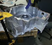
Here is the casing of the MG1 (larger motor) of the RX400h transmission. I cut away some of the unnecessary bits so it would fit better under the car, and weigh less.
Housing_Mods.jpg

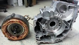
Here's a shot of the motor next to the housing. The open end is on the other side. The planetary carrier seat can be seen in the middle of the housing, with what seems like a very odd figer-size spline pattern.
MG1_and_Housing.jpg

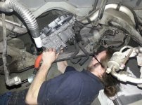
Here's a photo of Mike, one of the guys who was helping me in on some of the earlier parts, test fitting one of the motor casings near the transmission tunnel. It was then we found out there just wasn't enough room up there, so it was decided that the motors would have to exist behind the stock cross-member, where the engine went previously.
EngineBay_TestFit.jpg

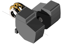
Here is a perspective view of the transmission assembly. It uses the stock 2.47:1 gear reduction with a planetary gear set. In this case, the carrier is fixed, the ring gear spins at low speed, and the sun gear spins with the motor. A small 11T sprocket (size 525 chain) is attached to the ring gear and held in place on the plate with the stock bearing from a GSXR600 transmission output shaft that was welded to the ring gear (sorry no pictures of actual welding, though I'm quite proud of it).
Transmission_Assembly.png

Here is a top view of the two independent motors, their plates and sprockets. I eventually plan to weld both plates together and use the stock transmission mount points on the outer edges of the motors to hook to the vehicle frame in the back.
View attachment 5

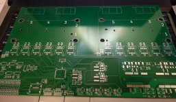
Finally, here's a photo of the inverter board in it's current state.
inverter.jpg

So, if anyone has any comments to share, I'd love to hear them.
 
If you value life experiences over money (I know I do), then building the car before getting a job seems perfect.

However, I personally just want to throw my 2 cents in for discouraging the ~650v battery. I know those motors are setup to run at 650v with a clever boosting inverter drive system from the lower voltage battery on board. They do that to save a few dollars and a pound or two in phase lead cross-sectional needs. However, you notice even Toyota doesn't want to mess around with a battery at those voltages, the step it up in the inverter, and I think they are doing it just to leverage the IGBT's voltage capabilities better.

What IMHO would be a much nicer end product would be re-terminating or re-winding those motors to operate from a lower voltage, like 100vdc perhaps. Then your BMS complexity needs decrease by orders of magnitude (because getting cell-stack interface chipsets to function with 650v of potential is NOT as easy as the datasheets for the chips would lead you to believe). You would need ~6x heavier phase leads and battery leads. That and the work to re-wind the motors are the only downsides I see. Your upside list is massive though, including the ability to survive an accidental shock from the pack, which I've come to believe is a pretty good upside to have. Your controllers can be simple then. Your battery management becomes much more simple. You have normal fuses and things available, and they actually work rather than exploding into plasma and things like HV fuses have bad habits of doing.

I would also avoid HK cells for this pack unless you want to spend the very serious amount of time to screen them for defects, including letting them have months of sitting to catch cells that will puff. Even then, I would ONLY do it with HK cells if I had made some pack interconnect topology that permitted swapping cells as you get various and random infant mortality events for a while. These are also all reasons why I don't like insta-kill pack voltages, because in real life with a DIY pack you end up working in it pretty often, and it only takes one fumbled safety interconnect or welded contactor or slip of the hand or whatever to be long-term dirt napping.

If you mounted the rear-ends side by side in-line at the output axles, I think you could simply bolt the two inner axle flanges together, and the differential function would still work normally with the outside axle from each motor/diff going to a wheel. It would minimize drive train complexity noise and failure modes if you can make space for them to fit, but I understand that may be a very difficult thing to package. If it's made like other Toyota rear ends, you can likely slide a stub axle shaft between the pair of spider gears to couple them and save a few inches of width if you by chance are that close to fitting.
 
Dnmun, Thanks for your comments. I suppose I should clarify. I do have a job, and a Ph.D. in electrical engineering. My job is a co-founder for a start-up company developing prototype electric motors. I have my hands full with work and money is not really the issue of concern. It's a question of motivation. The reason I'm inquiring here is to see if anyone else finds what I'm doing valuable enough to want to use it, or a future version of it, for themselves. The controller, powering motors that can be purchased for less than $1K each, represent a package that is significantly less costly than commercial systems from UQM, Solectria, etc. As for the battery management system, i have yet to see an active manager on the market currently that actively balances cells (and increasing the range of an aging pack or a pack with damaged cells).

In short, if it's just me who would use these things, its a whole lot of engineering just to say I did it.
 
Also, I know you may not know myself or other members of this awesome DIY EV community, but let me assure you most of us, including myself aren't "safety ninnys" on our DIY projects, and are quite comfortable working on things that explode wrenches if dropped between power terminals etc.

However, if you've never messed with a system at say 650v, it's pretty scary to be honest. Cells have no off-switch, so it's up to you to make the pack divide into non-leathal voltages for servicing etc. You also can NOT underestimate corrosion and weather/salt/water effects on your pack and HV terminations etc. Water likes to slip inside wire insulation jackets, or extra external insulation sleeves and form unexpected current paths to all sorts of places you wouldn't imagine would end up tied to pack voltage. Connections that don't typically have enough power to arc or flash to let you know they are there, but they are still plenty adequate to stop a humans heart working on it.

Also, 650v isn't high enough to have much corona related issues fortunately, but I would still recommend wiring it as though it did, just for added life safety.


PS: I think it's AWESOME you want to make a controller to run these toyota rear-ends. I have actually been thinking of putting one in a light aero chassis myself, but the controller related hassles is what stopped me.
 
Liveforphysics, thanks for your comments as well. My thoughts are listed below:

liveforphysics said:
However, I personally just want to throw my 2 cents in for discouraging the ~650v battery. I know those motors are setup to run at 650v with a clever boosting inverter drive system from the lower voltage battery on board. They do that to save a few dollars and a pound or two in phase lead cross-sectional needs. However, you notice even Toyota doesn't want to mess around with a battery at those voltages, the step it up in the inverter, and I think they are doing it just to leverage the IGBT's voltage capabilities better.
I have considered a battery boost converter, especially for the lower voltages (safety) and less individual cells to manage by BMS. Although, the drawback is that it would be full-conversion. Toyota only converts around 35% of their power to the battery. It mostly takes up the slack in difference in power between MG1 and MG2. In this case, it would be the full 250kW, which is no small converter. True, this could be done, but I guess I just left the idea alone as it requires the same amount of batteries, just in a more-series config than the 100V suggestion.

liveforphysics said:
What IMHO would be a much nicer end product would be re-terminating or re-winding those motors to operate from a lower voltage, like 100vdc perhaps. Then your BMS complexity needs decrease by orders of magnitude (because getting cell-stack interface chipsets to function with 650v of potential is NOT as easy as the datasheets for the chips would lead you to believe). You would need ~6x heavier phase leads and battery leads. That and the work to re-wind the motors are the only downsides I see. Your upside list is massive though, including the ability to survive an accidental shock from the pack, which I've come to believe is a pretty good upside to have. Your controllers can be simple then. Your battery management becomes much more simple. You have normal fuses and things available, and they actually work rather than exploding into plasma and things like HV fuses have bad habits of doing.
This is a very good point, but re-winding seems like the only option and to get it to fit back in the existing housing after it is re-wound is also a concern. I share your fear of HV and 650V does seem quite high, but that means I'll have to pay more attention to safety measures like mid-pack disconnects and properly strong housings for components with open terminals.

liveforphysics said:
I would also avoid HK cells for this pack unless you want to spend the very serious amount of time to screen them for defects, including letting them have months of sitting to catch cells that will puff. Even then, I would ONLY do it with HK cells if I had made some pack interconnect topology that permitted swapping cells as you get various and random infant mortality events for a while. These are also all reasons why I don't like insta-kill pack voltages, because in real life with a DIY pack you end up working in it pretty often, and it only takes one fumbled safety interconnect or welded contactor or slip of the hand or whatever to be long-term dirt napping.
I am also wary of HK packs, but after I had one of my colleagues run a 300-cycle test on some cells, I found they out-performed A123 cells for degradation, power density, and cost. It's really hard to turn away from that, and considering how feature-rich of a BMS I was concocting, I was figuring I would be able to notice any real issues before it(puffing, shorting, temp, fire) got too bad. (hope)

liveforphysics said:
If you mounted the rear-ends side by side in-line at the output axles, I think you could simply bolt the two inner axle flanges together, and the differential function would still work normally with the outside axle from each motor/diff going to a wheel. It would minimize drive train complexity noise and failure modes if you can make space for them to fit, but I understand that may be a very difficult thing to package. If it's made like other Toyota rear ends, you can likely slide a stub axle shaft between the pair of spider gears to couple them and save a few inches of width if you by chance are that close to fitting.
I'm not quite sure I follow. I am already planning to use a chain drive as a final reduction which is around 3:1 to get realistic speeds at the wheel. There isn't really a 'rear end' as it were, or differential. There's just two motors with independent gearing (planetary and chain) to get the shaft speeds to the right point. 123MPH top speed at 12,000RPM motor speed. If I missed anything about what you were trying to suggest, let me know. I know that the motors are too large to fit in the space in-line with the axles, which is why the chain drive-lines are positioned inward with respect to the motors/housings.
 
liveforphysics said:
Also, I know you may not know myself or other members of this awesome DIY EV community, but let me assure you most of us, including myself aren't "safety ninnys" on our DIY projects, and are quite comfortable working on things that explode wrenches if dropped between power terminals etc.

However, if you've never messed with a system at say 650v, it's pretty scary to be honest. Cells have no off-switch, so it's up to you to make the pack divide into non-leathal voltages for servicing etc. You also can NOT underestimate corrosion and weather/salt/water effects on your pack and HV terminations etc. Water likes to slip inside wire insulation jackets, or extra external insulation sleeves and form unexpected current paths to all sorts of places you wouldn't imagine would end up tied to pack voltage. Connections that don't typically have enough power to arc or flash to let you know they are there, but they are still plenty adequate to stop a humans heart working on it.
Point taken. I was mostly concerned about the chance of a software error sending my car careening down the street, but you bring up another thing for sure. I should mention that I do have a healthy fear of both high power batteries and magnets. Also, I have put together 768V battery banks before (in grad school) and also made an inverter that interfaced with it (though it was for grid-tie application, not motor control). Though you're right, experience is one thing, but it doesn't make 650V any less leathal.

liveforphysics said:
Also, 650v isn't high enough to have much corona related issues fortunately, but I would still recommend wiring it as though it did, just for added life safety.
Not sure what this means, maybe just adequate lead spacing?

liveforphysics said:
PS: I think it's AWESOME you want to make a controller to run these toyota rear-ends. I have actually been thinking of putting one in a light aero chassis myself, but the controller related hassles is what stopped me.
I was kind of hoping that people would find this cool enough to use themselves. Despite the voltages of these motors, they have a resolver position sensor that, from my perspective, is not all that easy to interface to. I put a circuit on this board that excites the excitation coil and 'hopefully' it works as intended to get the position of the rotor accurately enough and without too much noise from the inverter.
 
I agree 650V is not useful for anyone in the DIY community. Even the Model S is "only" around 400V

I have a couple honda IMA motors designed to run on 144V. One has a bad rotor but it is a spare stator and good for mockup. I was going to run one on a motorcycle but the custom case cost too much.

What you could do is stack a few. Use multiple motors and multiple controllers to keep costs down. These are nice motors with square windings. The efficiency curve is crazy good even at low rpm. The magnets are super high temp designed to work bolted to a engine. Expect lots in the junkyard as the honda nimh batteries are not holding up. They are in the civic, accord, crz, and maybe more. Much easier/cheaper to get than your lexus motor IMO

I think this would be useful for the DIY community. Grows to fit any vehicle or budget. Get more money add another controller and module. Others had the same idea but got no where as making the coupler is the hard part. Supposedly the newer IMA motors have even a wider stator for more torque. Should be able to mod for water cooling for more continuous power. I'm in the Bay Area if you are interested.

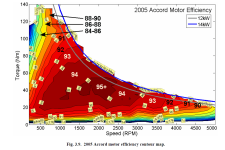
04_5.gif


2005 motor with round wire efficiency map. The newer motors should be good for at least 25kw peak or more with higher voltage. 144V is a sweet spot though for mosfets
2005 motor.PNG


The stator can be completely unbolted from the case super easy.
 
halcyon_m said:
Here is the casing of the MG1 (larger motor) of the RX400h transmission. I cut away some of the unnecessary bits so it would fit better under the car, and weigh less.
View attachment 2

Which one are you using?

Generator MG1: PMSM, max 650V, max 109 kW @ 13000 rpm, max 80 Nm @ 0-13000
rpm
Motor Generator MG2: max 650V, max 123 kW @ 4500 rpm, max 333 Nm @ 0-1500 rpm
(front wheel drive)
Motor Generator Rear MGR: PMSM max 650 V, max 50 kW @ 4610-5120 rpm, max 130
Nm @ 0-610 rpm (rear wheel drive)
 
Wow for that Honda motor. That's nutty good, I didn't expect that good to be possible. It should entirely kill the "adding transmissions helps efficiency" BS dead.

I like the concept of no mechanical differential. I've always been shocked at how much heat they make. Even chain drives make a disappointing amount of heat watching them with a FLIR on a dyno'ing motorcycle. Carbon/Kevlar belts do the best of all sprocket/pulleys power transfer systems. That heat is your horsepower and battery being wasted. If you put 3 of those very thin Honda motors per side, you could power them with a pair of the new-ish 150v sevcon Gen4 master/slave triple setups, bolting a driveshaft to each side directly to the wheel. You would have 6 sevcons capable of >50hp, and I bet those Honda motors love to get the phase current increased x3 or so. :) Use all that beautiful copper they do right. Get it hot enough to tan its enamel, everyone I've ever seen pics of looks like its never been powered.
 
Open source torque vector control
Built on top of open source can bus controller so it works with the stock gauges/pedals/etc
https://github.com/collin80/GEVCU
can bus to sevcons or custom controller that can run 2/4/6/8 honda motors in vector mode
 
That is fantastic! No more differentials in our EV conversions! :)

No more wasted power and petrol engine legacy limitations to hold EVs back. Differentials just waste your power for a while and eventually will fail (given enough time, i realise many industrial transportation drivetrains can last millions of miles).

Does anyone of you EV nerds know what the new plug-in accord uses for a battery and pack voltage and controller topology? Im thinking of buying the motor and drive unit from one to put in my Insight. Too many projects, and far too many hours at work... I would love to have the time to be working on your porche project. Savour it and enjoy every bit of it. :) You will undoubtedly have the rest of your life to spend too many hours working.
 
Beat mercedes and rimac with open source torque vector control
We could also scale down to use on rc cars as a dev platform
Without a diff and with bldc motors you actually want multiple stators per side or else a fail mode could spin the car
This is where induction motors are superior for sure
No controller fail mode will lock the rotor
In our case multiple honda ima motors per side is an advantage
[youtube]http://www.youtube.com/watch?v=IElqf-FCMs8&[/youtube]
Customized vector control is finally going to make racing exciting again since the best tuners will win
Not the most money
 
Flathill,

I'm using the larger of the front-wheel drive motors, the 'motor' versus the 'generator'. I may have mixed up MG1 vs. MG2.

Though, as we all know, the ratings depend on a lot of variables (e.g. Cooling, voltage, PWM frequency, etc.). I have calculated that the MG2 (larger motor) is practically only 109HP (81.4kW), but that is the one(s) I'm using. The 'generator' has a slightly reduced stack length for an estimated power rating of 68.8HP.
 
I apologize in advance for a newbie question: I had always assumed one of the considerations for selecting a system voltage (realizing that higher voltage is better performance and also lower amps to get the same wattage)...is the charging system.

A battery voltage around 200V might make it easier to design a charging system that can bulk charge from 220-240 VAC to the charger. And it might even allow the main pack to be configured from two 100V packs, so the "sub packs" could be bulk charged from two 110-120 VAC supplies to the charger(s) if desired.

This is why I had the idea in the back of my head that 96-ish volts was a good goal for an E-motorcycle conversion (can be charged by a 100V bulk charger, or two 50V chargers powering two temporarily isolated 50V sub-packs), and...200V/400V was a useful theoretical pack for a car...so, if I tried that, what are some of the biggest challenges I'd have to find solutions to?
 
halcyon_m said:
Flathill,

I'm using the larger of the front-wheel drive motors, the 'motor' versus the 'generator'. I may have mixed up MG1 vs. MG2.

Though, as we all know, the ratings depend on a lot of variables (e.g. Cooling, voltage, PWM frequency, etc.). I have calculated that the MG2 (larger motor) is practically only 109HP (81.4kW), but that is the one(s) I'm using. The 'generator' has a slightly reduced stack length for an estimated power rating of 68.8HP.

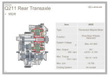
Nice on second thought...if you laid the groundwork for 650V systems man these Q211 motors from the lexus might be perfect for an ultralight 4wd EV conversion. I wonder the max speed with some 15" wheels and 650V. I don't see how lexus made any money on these hybrids. So complex. I hear the inverters are going out on them and are like 9 grand to replace. There was a recall but most are out of warranty. So we should see these in the junkyards also

ftp://www.energia.bme.hu/pub/eloadas/RX400h_hu051003.pdf

q211.PNG
 
So, I realize Toyota likely figured out how to make all those gearing stages and things survive for hundreds of thousands of miles, but holy shit it seems so needlessly complex and lossy/draggy and silly high motor RPMs for driving a wheel. The more I think about it, the whole 650v thing also just seems needless and foolish and costing them more stages of inefficiency and inverter cost pointlessly. Seems very weird they would do it over just 2-3x larger phase leads which would add minimal cost and weight compared to some giant voltage boost stage in the controller to fail.

A very non-Zen, very legacy ICE stuff and Prius inspired drive setup IMHO. Not at all EV-like in the way EV's have the capability to be (simple, elegant, silent, efficient).

I had not seen the drive layout inside one before, but I was hoping it would much more simple/elegant inside.

The biggest pity I see, is they did the work/cost/complexity of driving/controlling two motors, yet didn't remove all the stages of inefficiency/failure-modes and noise. They could have simply powered one wheel per motor directly, and if they were using motors like that Honda unit with the efficiency chart shown above, I bet TOTAL drive system losses could be lower than simply mechanical power transfer/drag losses in this arrangement, even if the Toyota motors were >95% efficient at all times they are running.
 
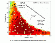
Capture2.GIFit is almost like they made them run at 650v so they would have no useful afterlife...

the efficiency map of a prius motor compared the honda motor. dont have any benchmark data on the lexus motors

the prius motor uses reluctance which is why it is more efficient at low torque levels
 
spinningmagnets said:
I apologize in advance for a newbie question: I had always assumed one of the considerations for selecting a system voltage (realizing that higher voltage is better performance and also lower amps to get the same wattage)...is the charging system.

A battery voltage around 200V might make it easier to design a charging system that can bulk charge from 220-240 VAC to the charger. And it might even allow the main pack to be configured from two 100V packs, so the "sub packs" could be bulk charged from two 110-120 VAC supplies to the charger(s) if desired.

This is why I had the idea in the back of my head that 96-ish volts was a good goal for an E-motorcycle conversion (can be charged by a 100V bulk charger, or two 50V chargers powering two temporarily isolated 50V sub-packs), and...200V/400V was a useful theoretical pack for a car...so, if I tried that, what are some of the biggest challenges I'd have to find solutions to?


Nope, 100% mistaken on all of that my friend. Only the charge power matters, the voltage the charger is outputting makes no difference and doesn't care a bit about input voltage. Most all chargers (even 36v units) have a PFC front stage that immediately takes whatever input voltage you gave it and makes ~380VDC on the PFC bus right away. From there it switches the DC bus it made at high frequency through an isolated transformer, which has windings to step it up or down as needed, and regardless of the voltage you want, only the copper fill% on the transformer dictates it's power handling, they can wind it for 1 super thick turn or 1000 hair-fine turns, and both will be identical power transfer and efficiency if the amount of copper is the same between them.


spinningmagnets said:
(realizing that higher voltage is better performance and also lower amps to get the same wattage)

This is a common incorrect conception that I myself once shared as well. Higher voltage does not mean higher performance. Higher voltage means higher voltage and all the things that come with it. Performance is about power and efficiency, and neither of those care what voltage you designed your system around. Lets say you need to make 200hp. That's ~149kW, quite a bit of power. You can make that power with a 72v system, or with a 720v system. In the 72v system, you need 10x greater current to make that power, and as you know resistive loss in a conductor is the square of current times resistance, so you see a 10x current increase makes a 100x increase in this top portion of the equation... This is where many people think lower voltage systems are somehow inferior, yet that 10x current increase system needs only 1/10th the number of turns to produce identical flux on the tooth, and 1/10th the turns means you can grow the cross-section of the wire by 10x to have the same copper fill, and the wire is 1/10th the total length. 10x thicker wire has 1/10th the resistance per unit of length, AND it's 1/10th the length means you've found that x100 multiplier to cancel the x100 on the top from the 10x current being squared.

They both work out exactly equal from the motor performance perspective as a result. The only downsides is the motor phase leads and battery leads need to be 10x thicker than before to have identical copper loss to the HV system. However, it's not like we're powering the motor on the other side of some huge building where cabling length/cost would be some big issue, in most EV stuff your cables are under 10ft long for about anything, some systems total power cabling length is under 4ft from battery to motor, so even if you need to run 3-4 passes of 00awg cable per phase lead or something for some super high power low-voltage system, your total cabling cost/weight is still going to be radically lower than growing additional BMS stage complexity and all the life safety related connectors and BS and hazards that come with higher voltages.

I think a big part of the reason you see goofy stuff like 650v used to make a ~100hp is because they leverage industrial motor inverter drive with IGBT power stages that were designed for running motors and equipment hundreds of feet away from the controller in many applications. In those situations high voltage makes sense. When your controller is 4ft from your motor, running high voltages for say under 300-400hp power needs just seems like adding cost, complexity, failure modes, and real life-safety danger just for the sake of adding them.
 
halcyon_m said:
liveforphysics said:
Also, 650v isn't high enough to have much corona related issues fortunately, but I would still recommend wiring it as though it did, just for added life safety.
Not sure what this means, maybe just adequate lead spacing?

By corona related issues, I mean electrical field concentrations at sharp edges and anything needle-sharp just starts hissing and eating your insulation up with plasma that it generated by ionizing whatever material was in it's field. When a voltage gradient gets too extreme (and it's claimed this can happen to needle-sharp points at low as 250-400vdc) the field lines have such steep gradients depending on the physical geometry it tears up the stuff you try to insulate it with, or just makes the air around it hiss, and that partially ionized air is amazingly good at helping a big fat spark arc to something that working the stand-off-voltage calculation would lead you to believe you had perhaps 5x the creep distance margin, yet get some sharp edge geometry involved and BAM! Totally unexpected arc-flash. I've been playing with HV a bit lately (for physics experiments not EV building), and I've been a bit boggled by how gnarly corona can be to try to control, and switched my approach from attempting to insulate it better to simply making only smooth rounded transitions to avoid generating it in the first place.

Here is a quicky corona primer:

http://www.highvoltageconnection.com/articles/corona.pdf

halcyon_m said:
liveforphysics said:
PS: I think it's AWESOME you want to make a controller to run these toyota rear-ends. I have actually been thinking of putting one in a light aero chassis myself, but the controller related hassles is what stopped me.
I was kind of hoping that people would find this cool enough to use themselves. Despite the voltages of these motors, they have a resolver position sensor that, from my perspective, is not all that easy to interface to. I put a circuit on this board that excites the excitation coil and 'hopefully' it works as intended to get the position of the rotor accurately enough and without too much noise from the inverter.

Thank you, and you know as well as I do that some junk-yard sourced affordable bolt-in EV drive rear-end solution is a holy grail for the DIY EV community and I would love to see it happen! I just wish Toyota would have been a little more thermodynamically Zen in design before making a design with so many power-transfer stages, from pack voltage to getting boosted to 650v, then multiple gearing stages linking a pair of motors and changing RPM range to something useful to wheel speeds, and then a differential in an oil bath to drink up more power as well. I have some experience with how much power it takes simply to spin a bunch of power transfer stages at speed, and I would rather have that energy in my pack going to moving the vehicle rather than heating a big aluminum oil bathed heatsink. I personally want to try to make a system that cuts out most of the losses they added into there system, I like the idea of driving each rear wheel with it's own direct drive motor driving a CV shaft to the wheel. I think that direction is the eventual path EV's will take as they mature, as it simply makes sense to delete every added loss stage and failure mode, which I think are only there because of OEM's largly working from legacy gas engine powered drivetrain parts and making them electric powered rather than simply designing to be electric from the ground up.
 
thermal imagers are good for detecting corona discharge but a microphone is even better (used in industry)
http://www.biddlemegger.com/biddle-ug/569001_UG.pdf

fun project is a plasma speaker
 
Liveforphysics,

One thing you have to consider about the difference between the Honda and Toyota motors is that the Toyota motors are higher power density. They achieve this mostly by operating at high speeds. It may be more lossy, but in the automotive industry the costs are beaten down to the lowest possible value. That means driving efficiency as high as it 'practically' can be for the cost. There's a saying about electric motors that you "pay for torque" which is largely true because it requires a certain amount of material (iron, copper, magnets) to achieve a given torque value. From that perspective, using a high speed motor and gearing it down can lead to a lower cost overall solution than direct-driving. Just take a look at direct-drive wind turbines for examples there. It was almost cost effective to avoid potentially shoddy gear boxes and go with direct drive generators until magnet prices went crazy. In my application, I'm getting something like 8x less speed for 8x more torque. From my perspective, I'd rather have a gear box rather than pay for 8 motors running 8x slower.

That being said, if motors could be designed fairly effectively to operate at higher torque levels using a cost-effective process, then less gear reduction would be necessary (only a single stage), or possibly the gear box could be removed entirely. This is largely hypothetical, because if it was that easy, then it would be an existing product. The closest we have to that is the bike hub motors with 20+ pole designs where the extra magnetic material (steel/iron) is lessened by the smaller and more frequent magnetic loops. However, iron losses become a significant issue at the speeds(frequencies) achieved by the 10 pole toyota motors, where eddy currents in the steel cause heat and drag losses. From that perspective, having more than 10 poles doesn't seem to make much sense, at that speed at least. So if the 'electrical speed' (frequency) is limited, then I can see why practically the most cost effective design has evolved to where it is now (considering air gap tolerances and such).
 
the motors we need for direct drive ev's are not here yet
I agree
Maybe the YASA but we really need AIR CORE THIN GAP LARGE DIAMETER BLDC MOTORS

check out boulder wind power
they are so efficient with PCB air core stators they don't need high temp neo magnets with $$$ dysprosium
watch dirty jobs the tv show where they service the gear box wind turbines
oil dripping everywhere
service nightmare with 3-4 guys to service one tower crawling all around mopping up oil mist so it won't attract dust destroying the gearox
every wonder why half the wind turbines here in the bay area at altamont pass no longer spin
many were abandoned as soon as the gearboxes started failing or when the service contract had to be renewed
BWP_PMDD_Rendering_Branded-600x297.png

BWP-Open-Circuit-Voltage-MeasuredvsPredicted.jpg

DDCL-Public_Domain-600x438.JPG
 
Back
Top