I appreciate the help.
Im going to break this down a little to reply...
dnmun said:
the pictures that helped the most are the last ones with the bottom exposed. it appears in the last picture that over on the left side in the red case there is a small battery charger built into the case. is that how it charges the battery? you plug an AC cord in there? one of the red wires comes from that charger over to the solder pad marked Batt+?
Yes. the system is broken down into a simple charger board on one side, and the controller on the other. I will be removing the charging part when swapping over to lipo. My charging solutions are all external.
Between the two in the shrink wrap, is a "smart charger" circuit. and a diode.. its all a very simple thing, im not worried about that side as I can just unplug it without issue.

dnmun said:
on the back you can see the label Batt+ on that wide solder landing where the two red wires are soldered, then there is another isolated solder plane in the middle and another big solder plane on the left with M1+ label. that is how the current flows from the battery to the positive terminal of the motor. this is for a brushed motor obviously.
Yup, simple brushed motor.
dnmun said:
on the other side of that metal plate, on the back with the 4 screw holes with the insulating rubber shield, those solder planes are all connected together to the M1- black wires going to the negative terminal of the motor.
yup.
dnmun said:
those relays on top connect the B+ of the battery to the motor M+ and i think, pretty sure, that is how the HVC and LVC controls are exercised.
This, I am not sure about. I think they're controlled by the controller for more than just the cutoffs. I think they're also how the controller "turns on".. kind of like contactors... if they were on all the time, i believe the controller would kill the batteries.
dnmun said:
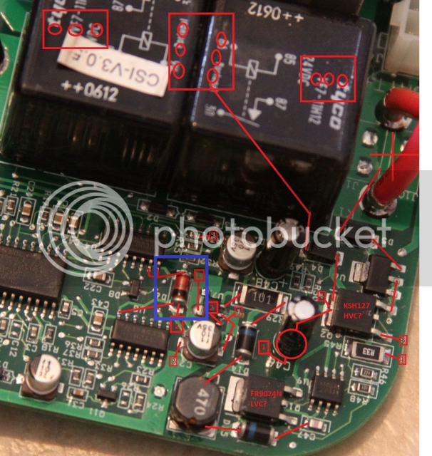
this is not built like the normal BLDC controllers we see so it does not have the same type of microprocessor controlling the commutation of a brushless motor. so the way it sees and acts in response to HVC is not clear from looking at those pictures except i can see some traces running across the surface between the pads under the relays. the traces we are looking for will go from that Batt+ pad over to a small 8 pin IC called a dual op amp. it will have a label like 324 or something similar like 327 and the output from that op amp will go over to the transistors on the right side in the first pictures. those big diodes, like D5 are there to capture the flyback voltage spike from the relay turning off.
this is where it gets frustrating. ALL of the ICs have no writing on them. I didnt believe it, so I dragged out the magnifier and everything. they're all shiny..and just black. no visible laser etching. check out the pics I link to below. I couldnt believe it myself. So I have no idea what chips I am looking at, just a vague idea off guesses. EXTREMELY frustrating.
dnmun said:
we need to follow any of the traces going from that Batt+ pad over to the active ICs on the front side so if you guys can look closely at any connection that goes to an 8-16 pin SOIC and has a trace going from that IC back over to the transistors. once we have a clue then we can see what the other side of the input to the op amp is and adjust that so that would raise the HVC.
or we can just solder a wire across the relay terminals and totally defeat the HVC function so you can use it with any voltage. except to go to really high voltage we need to identify the mosfets and other parts.
if you can read the labels, on that side where silvia had labeled and circled stuff, on those ICs then post them up too.
we cant go too much higher on the voltage anyway... the caps are all rated for 35v. the coils for the relays are for 24v... I dont think I want to overdrive them past 35 either.
in anycase, there are no labels to read. you can really see that in the last image in the list below.
http://fastgm.com/travis/Goped/controller/20141214_203246.jpg -- overall view 1
http://fastgm.com/travis/Goped/controller/20141214_203254.jpg -- overall view 2
http://fastgm.com/travis/Goped/controller/20141214_203744.jpg -- Topside of controller 1
http://fastgm.com/travis/Goped/controller/20141214_203753.jpg -- Topside of controller 2
http://fastgm.com/travis/Goped/controller/20141214_203812.jpg -- Topside top edge 1
http://fastgm.com/travis/Goped/controller/20141214_203836.jpg -- Topside top edge 2
http://fastgm.com/travis/Goped/controller/20141214_203842.jpg -- Topside top edge 3
http://fastgm.com/travis/Goped/controller/20141214_204101.jpg -- Topside bottom edge 1