erwincoumans
100 W
- Joined
- Apr 2, 2015
- Messages
- 141
I have hub-motors using the TURNIGY AERODRIVE SK3 – 6374-149KV and each motor has a VESC attached, at 12s (or 6s if wiring parallel).
Being spoiled by the Boosted Board, I'm not entirely happy with VESC performance at startup and low speed braking, so I want to try adding sensors to the motors.
I noticed an older thread (http://endless-sphere.com/forums/viewtopic.php?f=28&t=34816), but I have still questions:
1) Which hall sensor to buy? Would this one work? http://www.amazon.com/gp/product/B00ATNJH20?psc=1&redirect=true&ref_=od_aui_detailpages00
(assuming it is 5V as in the picture and in the amazon answers, unlike the 24V in the description)
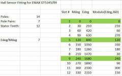
2) Where do we need to place hall sensors using epoxy glue exactly? I want to place them in-between the stator teeth, but that would not be exactly 120 electrical degrees (17 physical degrees according to http://endless-sphere.com/forums/viewtopic.php?f=28&t=34816 ?)
There are 12 magnets/gaps on the stator, and 14 magnets on the bus, see picture below.
3) do we need to add a 10k resister somewhere?
4) how to configure/tweak the VESC to use the hall sensors? When I stick the Hall sensors between the stator wires, it won't be exactly 120 electrical degrees I guess. How do we compensate for this? Will VESC 'just work' without any work? Does the order of Hall sensor wires matter?
5) how to route the hall wires outside, perhaps alongside the 3 existing cables?

Last but not least, does anyone know where to buy a low-KV sensored brushless motor that is compatible with VESC?
Any help is welcome.
Thanks!
Erwin
Being spoiled by the Boosted Board, I'm not entirely happy with VESC performance at startup and low speed braking, so I want to try adding sensors to the motors.
I noticed an older thread (http://endless-sphere.com/forums/viewtopic.php?f=28&t=34816), but I have still questions:
1) Which hall sensor to buy? Would this one work? http://www.amazon.com/gp/product/B00ATNJH20?psc=1&redirect=true&ref_=od_aui_detailpages00
(assuming it is 5V as in the picture and in the amazon answers, unlike the 24V in the description)
2) Where do we need to place hall sensors using epoxy glue exactly? I want to place them in-between the stator teeth, but that would not be exactly 120 electrical degrees (17 physical degrees according to http://endless-sphere.com/forums/viewtopic.php?f=28&t=34816 ?)
There are 12 magnets/gaps on the stator, and 14 magnets on the bus, see picture below.
3) do we need to add a 10k resister somewhere?
4) how to configure/tweak the VESC to use the hall sensors? When I stick the Hall sensors between the stator wires, it won't be exactly 120 electrical degrees I guess. How do we compensate for this? Will VESC 'just work' without any work? Does the order of Hall sensor wires matter?
5) how to route the hall wires outside, perhaps alongside the 3 existing cables?
Last but not least, does anyone know where to buy a low-KV sensored brushless motor that is compatible with VESC?
Any help is welcome.
Thanks!
Erwin