Tombombadil1988
1 mW
Hey guys,
for my second build I want to get things as convenient as possible. Therefor I would like to integrate a Lipo Balancer/Charger right into the board. Have you guys done this before?
So here's what I plan to do:
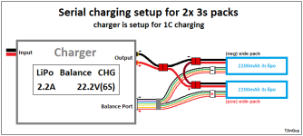
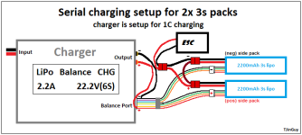
1. Wire the two 3s in series, including balance leads like seen in the attached image
2. Split the power leads and connect them to the ESC (VESC) and charger
3. Turn off the ESC, plugin the charger whenever I get home and let it charge
I'm not sure whether having the balance leads plugged in is going to be a problem?
Best, Tom
for my second build I want to get things as convenient as possible. Therefor I would like to integrate a Lipo Balancer/Charger right into the board. Have you guys done this before?
So here's what I plan to do:
1. Wire the two 3s in series, including balance leads like seen in the attached image
2. Split the power leads and connect them to the ESC (VESC) and charger
3. Turn off the ESC, plugin the charger whenever I get home and let it charge
I'm not sure whether having the balance leads plugged in is going to be a problem?
Best, Tom