Support on my 10S BMS

okp

100 kW
Joined
Oct 26, 2014
Messages
1,193
Location
Paris
Hey folks!

Just did my first 10S3P 18650 Sony VTC5 pack. Works fine. I am now willing to connect this BMS to charge without unscrewing my enclosure.

size : 53*63MM
Over charge voltage test: VCU 4.25V ±0.05V (4.20-4.35V // each 0.05V per step)
Over charge voltage resume: VCD 4.10-4.00V
Over discharge voltage test: VDD2.50V ±0.1V (2.5-3.0V // each 0.05V per step)
Over discharge voltage resume: VDU 2.80V ±0.V1

Operating current: ≤300UA
Short circuit protection: 40A±3A
Short circuit protection duration: 500MS
Temperature protection: 55 / 65 / 75 degree
Typical output current: 30A

Max. output current: 45A
Balance voltage for single cell:4.19V ±0.02V

Balance current for single cell:≤ 55MA

Charging current:≤10A
Dim. 53 x 63mm (L x W)

1456773657-57.jpg

1456773657-12.jpg


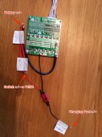
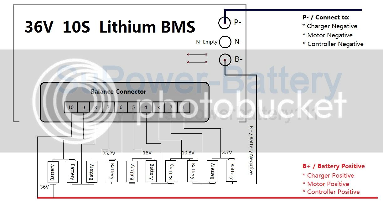
I do understand the battery balancing wires to connect... but for the other wires... I am just stuck, except for the B- which is the battery negative wire that goes on the BMS PCB as well as the B+ which is positive battery wire which goes on the charging plug. I understand than in fact the BMS "cut" the battery negative flow.

=> what are the discharging connectors for ? do I need to plug that somewhere?!!!
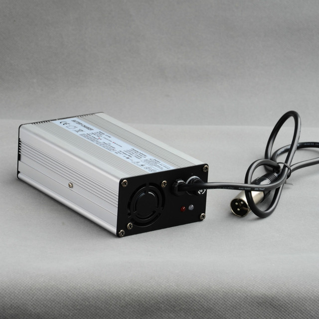
=> do you guys know where I can get or what kind of charger/specs can I buy as well as a "sweet" male/female connector ?
 
Just an example below, "switch" connects then to VESC(s). "P" or "Discharging" means the cables going to ESC/Motor.

You can use any 10s (42V) CCCV charger (with chinch plug for example), like this one: http://m.ebay.de/itm/131634833923?_mwBanner=1
 

Attachments

  • IMG_6488.jpg
    IMG_6488.jpg
    264.7 KB · Views: 4,445
Hi

I would be a little concerned about the discharge current here.

Short circuit protection: 40A±3A
As this is short circuit protection it would trip at the 40A sharply rising current. (Current flank) - but I would think that any sustained current over 40A would also trip it.
My dual draws 40A peaks per motor going uphill, that would be 80A out of the BMS.

Other than that looks like a neat bit of kit. Wonder if heat sinking it would help.
What are the part numbers on the MOSFETs?
 
hey, in fact I do have a fuse 40A on the antispark vedder's switch

is this fine as the female connector ?

http://www.conrad.fr/ce/fr/product/738870/Connecteur-basse-tension-Lumberg-NEB-1-R-embase-femelle-horizontale-int-66-mm-broche-19-mm-1-pcs?ref=list

or this one ?

http://www.conrad.fr/ce/fr/product/733946/Connecteur-basse-tension-072335-embase-femelle-verticale-int-55-mm-broche-21-mm-1-pcs?ref=list
 
I presume you are talking about the charging port?
The first product has a rated current of 3A, the second I can only see the technical drawing but it states "Rated Load: DC50V 0.2A" - so don't use that one.

If you are using the VESC you could adjust the max current to the max rating of the BMS.
 
thanks, I ordered a similar charger 42V 2A in france but it has other connectivity, the one on eBay was in germany. I am now looking for the appropriate cinch connectors...

http://www.conrad.fr/ce/fr/product/738596/Connecteur-basse-tension-Lumberg-NES-1-male-droit-ext-6-mm-int-198-mm-1-pcs?promotionarea=084

on this one it is stated 34V/DC... but the charger is 42V... just wondering if this connector will match.
 
Correct me if i'm wrong On this guys, i'm wondering as Well.. Since the ESC has a low voltage cut off wouldn't it be enough to Just use the BMS for charging only, that way you can use like only a 10 amp, cheaper, BMS. So Just connect the esc straight onto the batteries. And the charging port to the bms -> batteries
 
Mathieu said:
Correct me if i'm wrong On this guys, i'm wondering as Well.. Since the ESC has a low voltage cut off wouldn't it be enough to Just use the BMS for charging only, that way you can use like only a 10 amp, cheaper, BMS. So Just connect the esc straight onto the batteries. And the charging port to the bms -> batteries
You can, but you'll loose single cell low voltage cutoff.
 
Mathieu said:
Correct me if i'm wrong On this guys, i'm wondering as Well.. Since the ESC has a low voltage cut off wouldn't it be enough to Just use the BMS for charging only, that way you can use like only a 10 amp, cheaper, BMS. So Just connect the esc straight onto the batteries. And the charging port to the bms -> batteries

That's what I'm planning to do :lol: I'd rather get a non limited discharge BMS just for charging features and balance assist than anything else. Circuit and Exco have posted brilliant BMS solutions, but cost reflects the features so for now I just ordered this one and will use it for charging balance and more importantly, charging cut off!

Thank you okp BTW this is a great find!
 
It might make sense going this way (bypassing BMS for discharge), because any solution which allows regen brake power >10A flowing back into the batteries is more expensive and significantly bigger in size. And since good cells like the VTC5 or HE2 are almost never significantly out of balance it's imho not a big risk to do that.
 
yeah, I was as well wanting to use this item for charging only purpose (avoid me to open the box, which is fair).

so the discharge cables of the BMS will not be connected, meaning I will get the BMS in short on charging wires, between battery and powerswitch right?
 
hey!

I did my 10S3P pack and connected it the BMS, only CH- (i.e I didn't connect P-), So the BMS is only used for charging purpose between the antispark and the battery. By the way, the antispark gets positive and negative from the battery (and not from the BMS). It's pretty amazing how a 10S3P pack is fine for a single 6355 motor. I had to push the startup boost up to .0.60 and it's pretty fine.

I bought a 42V 2A charger and took the opportunity to setup a wattmeter on the flow to the BMS charging port. This allows me to get how much amps are going back to the board.

Even if I don't put the wattmeter, the charger gets really hot (like 50° celsius) after a short period of time. I noticed that it goes up to 3A sometimes and stay at 2.9Amps... not sure if this charger is accurate or reliable.

I got a 42V 4A charger from my Evolve Carbon but don't know if I can use it or if it will stop correctly... just trying to learn progressively how this works.

So, any thoughts about that ?
- use the evolve charger (hopefully the positive will be the middle pin as my exiting charger; don't want to shortcircuit anything)
- order a new charger 42V 2A (or 4A)... need to source one good in europe !
- use my existing Hyperion DUO charger connected to the BMS jack... just don't know which battery I should use, as li ion is limited to 7S and I am not using any balancing cable.... so no idea!

thanks!

1457287210-img-5326.jpg

1457287210-img-5330.jpg

1457287210-img-5333.jpg


42V-4A-Battery-Charger-for-36V-Li-ion-Lipo-Li-NiCoMn-Battery-Pack.jpg_640x640.jpg
 
hmm, you are using the evolve speed charger - that one is charging constant current only until a current cutoff is reached. i think it charges with 6A, might be quite high for only a 3P battery. the cheap evolve charger is best imo. stops at 41V with cv charging at max 4A i think!
 
hey white,

no in fact I am not using the evolve charger; I was just saying that I had this one that I can test... I am using this one

1457287210-img-5326.jpg


but it gets hot. David told me that it may come from the fact that the charger is not CC/CV but not sure about that as this charger is sold for hover boards;
 
thanks ! I confirm that the evolve fast charger works fine. I like also the fact that when I don't hear the ventilator sound it means that's its fully charged.

I have checked the cells with the voltmeter these are 4.1v individually and the whole pack is 42v (even if 4.1x10 equals 41 !).

I am now wondering what would be the deal if I use the -P as the discharger wire going to the vesc (instead of the battery discharge wire). It means that the BMS will protect the battery in case for cut off and things like that right? but this is useless when using a VESC isn't it ?
 
Back
Top