Keith_hill
10 mW
- Joined
- Oct 29, 2016
- Messages
- 34
Hi All,
I was hoping that someone could shed some light on to a problem I'm having with my throttle.
My throttle set up is this:
Throttle: http://alienpowersystem.com/shop/electric-throttle/electric-thumb-throttle-1-4v-hall-effect/
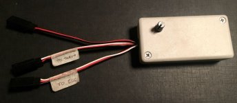
PWM Chip: http://alienpowersystem.com/shop/rc-ev-accessories/electronics/alien-throttle-interface-1-4v/
ESC is: http://alienpowersystem.com/shop/esc/alien-120a-3-12s-jet-esc-hv/
The problem is 100% of the power is applied at about 50% of the available thumb throttle travel, this means that it is difficult to modulate - this can be seen in the video I posted of my build. So when riding it, after 50% of the throttle is applied the scooter seems to be going as fast as it can and the rest of the throttle travel is just dead.
I checked tonight that the hall effect throttle is indeed a 1-4v output (thought that it could be a 0-5v by mistake) but the multimeter confirmed the spec.
Would this happen if the PWM chip was actually the 0-5v version by mistake?
Has anyone encountered anything like this?
- Keith


