Seeking information for Electric scooter build.

ElectricBeam

10 mW
Joined
Aug 19, 2017
Messages
23
Location
Bay Area, CA
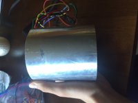
I have been riding electric scooters for years now, mainly models from supercycles and scooters running stock 48volt Li-ion systems and cheap controllers. I have become dissatisfied with the engineering and general performance/reliability of these scooters, and have embarked on my first serious upgrade. I am currently working on the build, but need expert advice on several issues. The stock system on my "1500 watt" scooter used a 48v circuit, with a controller and motor from Golden Motor. The motor was getting uncomfortably hot during operation, and after installing a power meter for testing, I discovered the scooter was pulling 100 amps during acceleration. This made for good performance but lead to overheating in the motor, wiring, and controller. For the project, I am looking to upgrade to a system with much higher voltage, which should allow me to reduce losses due to heating. I was hoping to run the 48v rated motor at over 100 volts to achieve this reduction in current while keeping a similar power and performance level. I am unsure of the possible electrical issues associated with overvolting to such an extreme, but I can say that the windings in the motor are in good condition, and the varnish has not broken down. To achieve this voltage, I plan to use a 30-35s lipo setup with a Lyen or self-modified controller. I actually have a Em3ev 18 fet 4110 controller that I bought before deciding to use high voltage, and I was wondering if I can replace the fets, caps, and shunt and run a higher voltage. As for the battery, I am unsure how to charge such a high voltage pack without the cells drifting out of balance. I have included photos of the motor (With the low gauge wire and temperature sensor I added) as well as the scooter frame I plan to use. These are attached below.

Boiled down, the three questions I have are:

Can a 48v motor be run at such a high voltage without electrical problems?

Can I modify my controller myself?

How does one safely charge a 30-35s lipo battery back?

Thanks for taking the time to read this

/ Connor
 

Attachments

  • IMG_5634.JPG
    IMG_5634.JPG
    33.1 KB · Views: 1,452
First, 35s is going to be almost 150v fully charged--three times what any of the stuff in there was designed for. It's not impossible to fix that, but it may require more than one controller sacrifice in the process of finding out (the hard way, probably) all of the things you'll have to upgrade (as parts fail from one thing or another). ;)

Switches and relays that control battery or motor level power should be replaced with ones rated for at least that kind of voltage, or else the arcing across contacts as they are opened and closed may weld them shut, and you won't be able to turn things off after tehy're turned on. Or else arcing on the contacts may leave nonconductive buildup and they may not turn back on after turning them off.


If it's a brushless motor, then tripling the voltage would be fine, as far as the motor itself goes, other than whatever possible problems come from the rotational forces trying to pull the rotor apart--if it's well made, that's not a problem, but if it's cheaply made, sometimes it can be.


If that is a brushed motor (Cant tell without seeing the core with teh shaft on it), the higher the voltage, the more brush arcing there will be, and the more heat there will be from that, which can damage the commutator and will wear out the brushes a lot faster than normal. Three times the original voltage is a lot for a brushed motor (double is, too).

Additionally, tripling the voltage will triple the speed at which the motor spins. Since the commutator was built to withstand rotation forces only a third of that new speed, it's possible that if it's built to just barely handle that, it could come apart, or "grenade" at the higher speed. This may never happen, or it might happen the first time it's run, or only after it reaches a certain temperature, or some other condition that could happen randomly.

If it does happen, you'll have to replace the motor with a new one (it won't be worth rebuilding). If pieces of the commutator come out of the motor casing, they may damage other things.


Regardless of motor type, since it will triple the motor speed, you'll need to change the gearing to lower the speed back down to normal at the wheel. (unless you're looking to nearly triple the speed of the scooter, and possibly lower it's performance from a start, and still draw high start currents, in which case you can leave the gearing as it is). If your sprocket on the wheel end is already big, you won't be able to triple it's size. It's likely the on on the motor is already as small as you can get, so you may have to add a jackshaft between motor and wheel to do a second reduction stage with.


Modifying the controller for triple the voltage it was made for will require changing the FETs and capacitors to something significantly higher than the voltage the batteries will be at full charge.

Otherwise the voltage spikes from the motor/etc could exceed the specs fo the parts and cause damage (caps may just age faster, or may swell up or even explode, but in any case they don't do their jobs of filtering spikes and dips, which can then cause problems in ohter parts like FETs. Usually FETs fail shorted, so you'd have uncontrollable full throttle if that happens).

You'll also have to change stuff in the controllers low-voltage power supply (LVPS) which changes battery voltage into 12v and 5v for other parts of the controller. Exactly what to change depends on how they designed it.

Sometimes it just has a big fat resistor between battery and it's input, in which case you just put a bigger fatter resistor, with about triple the resistance and higher wattage rating in it's place. Or put a second and third identical resistor in series with the first one. Either one would do the same thing.

If they used an SMPS switchmode power supply instead, you'd have to reverse engineer the frontend of it and see which components require upgrading to make them tolerate the tripled voltage input.

You would not do anything to the shunt--if you do, then the controller won't have any way to know how much current it is dealing with, and it's easy to blow stuff up that way. You could remove one of the shunts if there is more than one, and that would reduce the current the controller can supply, but that will also reduce system performance, with the benefit that the cotnroller will be safer from current spikes and whatnot. (doesn't have anything to do with the voltage, though, and that could still cause problems).


At a guess, youll need a new power meter, too, (assuming it's a typical RC wattmeter) as it probably wont' handle 150v. (most of the ones I've seen will only do about 50-60V max; a few will do 100V, and even fewer will do 150v. Maybe the Cycle Analyst HV version from Grin Tech.


If the batteries are all very good quality, and cells are all well-matched, then balance won't be much of a problem adn you could just bulk charge with any good charger, like a series of Meanwell HLG LED PSUs (a search of the forum for those will find a number of threads with good info on picking the ones you need).

Try not to run the cells down below 3.5-3.6v and they'll stay balanced better; the lower you run them the more unbalanced tehy'll get.

If they're average RC LiPo, they may get unbalanced regardless of how well you treat them, and may require a balancing charger every time they're used. There's a number of threads that talk about ways to charge a high voltage lipo pack, but it may take some poking around to find them. Maybe teh sticky index in battery tech section will help.

You could put a BMS on there to manage charge and discharge, and just use a bulk charger; I don't know what the cost / availability is for a 35s BMS. You'd have to look around the web to see what exists. I expect tehyre not common, and probably expensive.
 
Thanks for all the information. You got it, it is brushless. Since I don't plan to let the motor reach insane speeds, I am hoping it will not self-destruct. I am really only aiming to increase the efficiency of the system while maintaining a high power level. Of course, that is not to say I won't ever run it at high speeds. As for the battery, I was able to locate some 32s BMSs that appear to be suitable on Aliexpress. I know there are millions of BMSs on these sites, but I am not sure what the consensus is on buying them. Here are two: https://www.aliexpress.com/item/32S...54fc-4a80-8351-b1243ea4a037&priceBeautifyAB=0
https://www.aliexpress.com/item/201...54fc-4a80-8351-b1243ea4a037&priceBeautifyAB=0

With a BMS, I suppose I could get away with lower quality batteries such as these on sale now
https://hobbyking.com/en_us/zippy-compact-5800mah-8s-25c-lipo-pack-xt90.html

But besides that, what is a source of high-quality lipo batteries? I would not be against using them if the price is not insane.
 
ElectricBeam said:
Since I don't plan to let the motor reach insane speeds, I am hoping it will not self-destruct.
That really only happens to brushed motors, but some brushless inrunners aren't built very well and magnets can come off the rotor at really high speeds.

I am really only aiming to increase the efficiency of the system while maintaining a high power level. Of course, that is not to say I won't ever run it at high speeds.
Well, higher voltage vs higher current doesn't necessarily mean higher efficiency.

It depends on the exact problem, and the reasons it's happening.

There've been a number of discussions about it, but basically it comes down to losses inside the electronics at higher voltages, vs losses inside teh wires at higher currents, vs the winding of the motor vs the speed it's run at vs the gearing of the motor-to-ground system.

Thicker wires will fix those wire losses.

Electronics losses cant' really be fixed that easily, at least not all of them.

As an example: often, FETs for higher voltages have higher internal resistance vs those for lower voltages. So there's more heat generated in them whenever current is flowing. Not much to do about that but find the best match for FETs for your needs, that will still work with the existing gate drivers/etc., or get a controller that is already optimized for it by a good engineer (this is probably not cheap).

Similarly, if a controlelr's LVPS is not a switching unit, or even if it is and it uses a resistive input like the non-SMPS ones do, then the higher the voltage the more heat it'll generate. This can be fixed by using a controller that has an SMPS LVPS in it, or installing one in the controller and bypassing the existing LVPS, as a couple of ways.

Those losses are not on the scale of making things super hot, but they do exist.


But...since it's a brushless motor, you may want to look into the phase/hall wiring combo first. If it's a false positive, it may run forward, even at normal speed under load, but it will take way more power than it should, and everything will get hot (wires, motor, controller) because the timing of the system is wrong.

That might fix everything without all the complexity and hassle and expense of tripling your voltage and replacing or modifying all those things.


As for the battery, I was able to locate some 32s BMSs that appear to be suitable on Aliexpress. I know there are millions of BMSs on these sites, but I am not sure what the consensus is on buying them.

The consensus generally is that you get whatever they send, and it does whatever it does, and you pay whatever the cost is. Whether it does what you want, or instead just produces smoke, well, that's the gamble.

Sometimes sellers are honest, and sometimes they are not, and sometimes they have no idea what they actually have or sell. There's unlikely to be any kind of real support or warranty, honest or not.

I couldn't tell you if either of the linked BMS are what you need (even assuming the sellers have accurate info on the page, which is not a given).

You might have to look around the forum at the various BMS threads, and see if anyone has a recommended seller that's proven reliable. Then see if that seller has a BMS that does what you want.


With a BMS, I suppose I could get away with lower quality batteries such as these on sale now
I suppose, but remember that the battery is the heart of the system, and if it can't supply the power you need when you need it to, for as long as you need it to, the system cant' do anything to make up for that. ;)


But besides that, what is a source of high-quality lipo batteries? I would not be against using them if the price is not insane.
I don't know anyplace to get guaranteed tested quality RC LiPo--it's cheap for a reason: there's really no QC of the cells, assembly, wiring, or completed packs, regardless of source, AFAICT.

The main advantages are that tehyr'e easy to hook together, there are common balancing chargers for them, and they can put out some pretty high currents (for a short time).

But tehy have short lifespans, and when they have more severe quality problems, or are abused in the wrong way, they tend to go out in style, as it were. ;)

That said, various reports here on ES have said that the Turnigy version of a pack can be better than the Zippy, IIRC. (you could search for those two terms together and see what comes up).


I've used RC LiPo on CrazyBike2 and it worked pretty well while I did, but it didn't last all that long before it began puffing up; I doubt I could get the packs out of the ammocan they're in now wtihout damaging them. :/ (been sitting a few years now without much use since they started to go).


I've also used a cheaply made 18650 pack, and with low demand it works ok, but high currents it'd need a lot more parallel cells. Mostly this is not used much nowadays except for bench testing stuff cuz it has a wierd BMS problem.

I've used an old A123 pouch cell pack, and it worked pretty well. Still in use on the Raine Trike.


What I really like and use heavily are EIG NMC pouch cells but they aren't cheap and are hard to get hold of. If they were easier to find and get, I'd recommend using them. The only "easy" place to find them is used Zero motorcycle packs from the year or so they made them with that cell.

Others use various repurposed cells and pack sections from large-EV packs, like the Nissan Leaf, etc.
 
Thank you again. I will look around for more info on BMS suppliers. Thanks for all the information regarding efficiency. I actually considered that the motor may have been out of phase, but the current draw seemed reasonable for the speed I was getting. The motor is also only 85% efficient at 48v, which could explain some of the heat. Besides that, it is too late for me to revert the scooter. I guess I wasn't clear on what I was asking. The "Main" problem I am trying to solve is that of excessive heat produced in the motor. Since the motor needed 100 amps to reach 5kw at 48 volts, I figured that reducing the current to 50 amps at 100 volts would significantly reduce the heat generated in the motor while still producing 5kw. Is this not true?
 
Ah, I see.

That motor isn't meant for that high a power level, so the waste heat from it will still be a lot, at 85% efficiency. Assuming all 5kw is actually making it into the motor, then that's 750 watts of heat being made in the motor.

It doesn't matter if you're using high voltage or high current, the waste heat will be the same at that efficiency, if the power total is the same, for the time that you are using that power.

Remember that the only thing that changes is the battery current, not the motor current. Motor (phase) current can be much higher or much lower than the battery current at any moment in time, because the cotnroller is converting the one into the other.


You'll want to find a way to cool the motor; at least forced air through it and possibly heatsinks around it. Being an inrunner it's at least easier for heatsinks to do their job.

Keep in mind also that motors arent' just one efficiency at all speeds, there is a curve for each one. GM might have one available for that motor on their site; you'd have to check or ask them.


Changing the gearing would change the load on the motor, which would change the power required (or at least the lenght of time that power is needed) to reach a particular speed.

Just like riding a bike, it's really hard to get started from a stop if you leave the gears in the highest speed gear. But if you shift down to the lowest gear and startup, it's a lot easier. Of course, the top speed is then limited by how fast you can pedal.

So there is a compromise somewhere between how fast you want to go, and how easily you want to get started from a stop.

Using a higher voltage, and a gear ratio that lets the motor spin three times as fast but the wheel spin the same speeds it used to means it'll be a lto easier on the motor during startup, and it shouldn't heat up nearly as much.
 
Well thanks for the info, but I don't know if it is worth continuing this project anymore. The whole idea and path to improvement were based on that misconception, and I feel like I am back at square one yet again. Cooling the motor in my case would require drilling holes and mounting a blower, which could jeopardize the structural integrity, a move which seems unwise at 5kw. This also means that there is no reason to use high voltage, which leads me back to having no idea what power source to use. Thank you for clearing this up before I discovered it after buying everything. Part of me wants to replace the motor, but using a motor rated for higher power would result in me having to modify the frame, an area with which I have no experience. Thank you again.
 
So, back to the gearing...why not just change that?

Bigger rear sprocket, smaller motor sprocket, for better startup torque but lower top speed, less waste heat from lingering at the low motor speed.

Then up the battery voltage just enough to make up for the lost speed.
 
Ok, so after running off angry thinking this whole thing was a waste of time, I spent some time considering the situation. I have an idea to cool the motor using forced air from a high rpm brushless centrifugal fan.
https://www.aliexpress.com/item/Hig...1c47-49a1-912a-fb1aec7256c9&priceBeautifyAB=0
What I am unsure of is how significant of a difference this will actually make. The motor was previously sealed and had no circulation. Although the fan I plan to use is of high power (65 watts) and high pressure, I am concerned as the gap between the rotor and stator is probably only about 2mm, and must travel along the entire length of the motor through this small gap. I also will also use a front sprocket with 9 teeth, and a rear with 39, a decent reduction. This is actually a little lower than the stock gearing and should keep the motor spinning fast.

Barring losses in circuitry and efficiency curves, you mentioned that the efficiency of the motor will remain constant at the same power level regardless of the ratio of voltage to current. Does this mean I can use a 72v system with an 80 amp controller and not suffer increased losses in the motor? This may result in a slightly lower speed, but I like using 18650 packs whenever possible.

Thanks for everything!
 
ElectricBeam said:
I have an idea to cool the motor using forced air from a high rpm brushless centrifugal fan.
I'd use it to suck air thru rather than push air in. I don't know why but this tends to work better with most fans.

Also, if you do this, and if the fan has a thermal sensor / control, then you can put the sensor at the intake side, so that the fan runs on low speed, using less power and much quieter, until the motor gets hot enough to actually need the additional cooling.

I don't know if that particular fan is a good one or not, but typically the "squirrel cage" type fans like that move more air than the axial-flow fans like computer case fans and such.


Although the fan I plan to use is of high power (65 watts) and high pressure, I am concerned as the gap between the rotor and stator is probably only about 2mm, and must travel along the entire length of the motor through this small gap.

This is actually a good thing, because it means the air will be forced into contact with a lot of surface area, and be able to remvoe more heat, than if it had a big gap for air to easily flow thru.


If you don't want to open up the motor, you can isntead just use heatsinks on the outside, because the stator is mounted to the casing, so it will transfer heat out that way too. Then if necessary you could fan-cool that heatsink.

There's a number of threads that show various heatsinks that can be used on this "can" style of motor, but no easy search to find the good ones with pics/links/etc. :(

Some motors people have used them on are Cyclone motors, various inrunner RC motors, Kollmorgen (Kollmorgan) motors. I can't recall teh names of the other motors I've seen that way.

A google image search on such motors and heatsinks finds some stuff:
https://www.google.com/search?q=RC+motor+heatsink&num=100&newwindow=1&prmd=ivns&source=lnms&tbm=isch&sa=X&ved=0ahUKEwjQlIrp1rncAhXkxFQKHbtDBycQ_AUIBQ

https://www.google.com/search?q=inrunner++heatsink&btnG=Search&newwindow=1&tbm=isch

https://www.google.com/search?q=ebike+cyclone++heatsink&btnG=Search&newwindow=1&tbm=isch

https://www.google.com/search?q=endless-sphere.com+motor+heatsink&btnG=Search&newwindow=1&tbm=isch


I also will also use a front sprocket with 9 teeth, and a rear with 39, a decent reduction. This is actually a little lower than the stock gearing and should keep the motor spinning fast.
That should help. What ratio was the original reduction, vs the new ratio? The difference in the ratios will give you the new approximate top speed of the wheel, and can indicate how much difference it might make in power demands.


Barring losses in circuitry and efficiency curves, you mentioned that the efficiency of the motor will remain constant at the same power level regardless of the ratio of voltage to current.
Not exactly: if the power level is the same, and the efficiency is the same, the losses will be teh same.

The actual efficiency depends on the specific motor's efficiency curve, which changes depending on load and speed and voltage and current, etc. As noted, you'd have to check with Goldenmotor to get your motor's efficency curve chart.

You can see the basics of what I'm talking about at the simulator at http://ebikes.ca/simulator, by setting up various motor/cotnroller/battery systems and looking at the charts for different load and speed and throttle settings. (there are instructions/explanations below the chart).


Does this mean I can use a 72v system with an 80 amp controller and not suffer increased losses in the motor? This may result in a slightly lower speed, but I like using 18650 packs whenever possible.
It'll depend on the specifc motor's efficiency curve under the load you'll have it under.

If you run the motor at a higher voltage, but keep it geared the same or similarly to what it was at a lower voltage, then it will have a *higher* current draw at the startups from a stop, or on hills/etc that slow down the wheel.

This is because:

--phase currents are not the same as battery currents, so a lower-battery-current controler at a higher voltage doesn't mean a lower phase current than a higher-battery-current-controler at a lower voltage. It depends on the controller's design and settings (if any); most cheap controllers don't even monitor phase current so they dont' ahve any way to limit it (even though they may have a setting for it!).

--BEMF (back-EMF) is created as a motor spins, and is a voltage that gets higher the faster a motor spins, and essentially cancels out some of the phase currents. At startup there is no BEMF, so phase currents are (if not limited at the controller) whatever the maximum possible current would be for the resistance/inductance of teh motor phase coils, at the voltage placed across them by the controller. If you're at full throttle, that's the maximum voltage possible in the system, so ti's the maximum possible current (much much higher than battery current, typically).

--Low BEMF means high current means high torque, but it also means more waste heat depending on the efficiency of the motor at that current. There is always some current at which the motor is saturated and can't make any more magnetic field repulsion (torque) with that current, so it just becomes heat. That's different fro each motor.

--gearing to the ground (wheel size and any other gear/chain/belt/etc reductions) changes how quickly the BEMF goes up, and so how quickly the motor stops making so much waste heat, becuse it changes the curve upon which the motor reaches it's max RPM for the particular throttle input you ahve on the controller at the time vs the voltage of the battery.


So...a higher voltage can actually make the problem *worse*, if the gearing isn't changed to compensate for the voltage difference, and/or if the controller doesn't limit phase current in a useful way, etc.


Go check out the Grin Tech simulator, and spend a while for a few days playing aroudn with it. It takes a bit of time to start making heads or tails of exactly waht it's showing you, but once you get it, you'll be able to see what I'm talking about.

Justin_LE here on the forum has at least one thread about the simulator that explains some thigns about it, that might be helpful if teh instructions under the chart/etc aren't enough. .
 
Back
Top