Overvolting a minn kota trolling motor

From that screenshot it doesn't look as if you set the speed correctly, it's at the default of 60 m/S, rather than your boat speed of about 6.7 m/S. Also, you need to set the hub or spinner diameter (I used 50mm) and choose a blade aerofoil profile in the "airfoils" tab. I normally use Clark Y for the root, and E193 for the remainder of the stations to the tip, at an Re of 100,000 (Re might be higher for your prop, you may need to check the chord width it comes up with in the geometry tab and then check the local velocity to see if 100,000 is a reasonable guess for Re).

A three blade 250mm diameter prop, at 6.7 m/S and 1500 rpm, with 6000 W , would need a pitch of 390 mm (a bit on the coarse side) and would have an efficiency of about 70%. Thrust would be about 629 N.

Generally, getting the pitch close to the diameter seems to give close to optimum results a lot of the time, and is a good indicator you're going in the right direction when changing things.

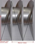
The prop in that picture I posted above runs at just over 85% efficiency, but isn't that practical for everyday use.
 
Thank you for the help, now I get Javaprop to work and also give me a geometrical look.

I tried to fiddle around with the program to see if I could design something similar to Metal Machete from Motor Guide.
No matter what I tried I could not achieve the wide angled blades in Javaprop.
It would be interesting to see what the calculated efficiency would of this type of prop.

Do you have any clue how to simulate these wide blades?
 

Attachments

  • MGA087M.GIF
    MGA087M.GIF
    28.5 KB · Views: 15,590
  • MGA087M Pitch.jpg
    MGA087M Pitch.jpg
    30.8 KB · Views: 15,590
Javaprop always tries to give a blade shape that is the most efficient for the chosen rpm, diameter, power etc, so tends to give narrower blades, as these are always more efficient than wide blades. Commercial props tend to use wide blades because, although less efficient, they tend to work over a wider range of conditions. Prop makers produce standard designs, and know that their props will never really match the boat they are used on, so this is a reasonable compromise.

If you go into the "modify" tab you can make some limited changes to the blade chord, angle etc, then you can re-do the simulation on the first tab by hitting the "design it" button and seeing how it compares.
 
I have some bad news. The 5:1 planetary gears I had was only rated for 3700 max rpm input, which means 740 rpm output.
The real downside was maximum output load, only 18nm (13.276 ft-lbs).
740 rpm at 13.276ft-lbs translates to 1400W shaft output from these gears. Way to small for my needs.

Yes, I know it's fairly easy to make belt reduction gears but I wan't to build a slender submerged outboard for easy use.
There is two big advantages. One is the water cooling at higher powers and the other is cushioning of noise for an enjoyable ride.
Another advantage, maybe not so important, is the weight distribution. Having the heavy duty part placed at bottom ensures
the outboard being stable in various operating conditions.

I have attached a couple of 4-blade prop designs. They are both the same except velocity, being 4m/s and 8m/s.
Can I ask you why the efficiency increases and loading drops when the pitch increases? It sounds a bit odd.
Increased pitch has more water to work against and should increase loading on the blades but it doesn't according to Javaprop?
See the attached prop files for Javaprop. The 4m/s file shows really high loading, even though it has lesser pitch and speed.

Regarding reduction gears, I have been looking around to find a supplier of parts to a DIY planetary gear (strong enough) but I haven't been lucky.
Best of all would be a gearbox made from helical gears that is virtually silent compared to regular gears. But those are even harder to find.
I might be possible to harvest a planetary gear from a scraped car but I wouldn't know what type of car to look for (with helical gears of the right size).
The outer dia of the planetary ring should be no bigger than 90mm to fit my motor design without to much hassle.

Thanks for listening to me, Jeremy :)
 

Attachments

  • Honk 4-blade prop - 8ms.zip
    973 bytes · Views: 267
  • Double helical gears for silent operation.jpg
    Double helical gears for silent operation.jpg
    4.4 KB · Views: 15,576
Glad things are beginning to make sense for you, pity about the gears though. When I was looking at options I found that good gears were very expensive and cheap gears were noisy. One possible source of a planetary gear set might be an old car automatic transmission. I know that one homebuilt aircraft engine manufacturer used the gears from an auto transmission to make a reduction drive, using, I believe, the gears from a Ford. There are some photos of it here: http://www.rotaryaviation.com/RD-2B.htm

Generally efficiency is closely related to blade loading - a high blade loading tends to give poor efficiency, a low to medium blade loading tends to give the best results.
 
I can't stop myself from fiddling around with Javaprop.
Here is a 2-blade prop design for 4500 rpm at 77% efficiency.
If I can find a good prop design for 4500 rpm I don't need any gear box as my motor is really strong.

What do you think about this design? Is it practically OK or just a bad result from Java prop?
Is 8 m/s velocity possible at 6KW or do I need to decrease pitch for more thrust at lower speeds?

I'm grateful for all feedback I can get from you. You have actually built a good working propeller from Java Prop!
 

Attachments

  • Honk 2-blade prop - 4500rpm 8ms.zip
    987 bytes · Views: 319
  • Honks 2-Blade at 4500RPM.GIF
    Honks 2-Blade at 4500RPM.GIF
    116.8 KB · Views: 9,151
Unfortunately, Javaprop doesn't take account of any practical issues, and assumes that you can always make whatever prop design it comes up with. If you look at the blade width for this high speed prop you'll see that it is extremely narrow, around 15 mm wide at most (go to the "geometry" tab and look at the values for "c", which is the blade chord). The E192 aerofoil section is very good, but is a 10.22% thickness section, so for a blade chord of 15mm the blade thickness would only be about 1.5mm, too thin to take the loads and too flexible. You could use a thicker aerofoil section, like the 12% Clark Y, with only a small (around 1%) efficiency loss, but this still doesn't give a blade that's strong or stiff enough at this narrow blade chord.

I've made a few props, mainly using stainless steel blades, and the thinnest blades I feel comfortable with for reasonably high power use are about 2.5mm to 3mm thick over most of their length. This means the blade chord needs to be around 25mm to 30mm over much of it's length.

For 6 kw I'd advise not going thinner than 3mm over the inner 2/3rds of each blade, assuming stainless steel, so the blade chord needs to be over 30mm for as much of the blade length as possible. This probably need to be increased to around 5mm to 6mm if using aluminium alloy for the blades, pushing the blade chord up to 50mm or even 60mm.

I know what you mean about fiddling with Javaprop, I must have spent tens of hours trying different prop designs!
 
The obscession I got about 4500 rpm is that it lets me use the regular Metal Machete Prop as standard prop without reduction gears.
Later on it might be possible for me to increase performance somewhat by a custom-made high speed prop in stainless steel.
I will continue my chase for a good prop and if you don't mind I would like you to evaluate my results for errors.

Safe cruising....:)

I started a separate topic for this propeller design.
Please see: http://endless-sphere.com/forums/viewtopic.php?f=39&t=40788
 
Thanks for the valuable topic enrichment Jeremy & Honk :D
I learned a lot about how a simple trolling motor operates and that a few simple adjustments can increase efficiency easily.

Sadly i cant use my/our Minn Kota trolling motor for experimenting because it is owned and shared within my friend group.
I put up some ads on seller websites. Hopefully someone responds and sells me his broken trolling motor so I can start my experiments. :roll:
 
Jeremy Harris said:
Power absorbed by the prop is proportional to the cube of prop rpm, so doubling the voltage doubles the rpm but the motor uses eight times the power.
This means that motor current will increase by a factor of 4 if you double the voltage.
I'm very interested in this phenomena and I will soon do another voltage doubling test where I closely monitor the motor current and motor voltage.
I will use a 1mR 1% accuracy shunt for the current measurement and each mV measured across the shunt equals 1amp of current going into the motor.
The different voltages I will test is 6V, 12V and 18V. I will also measure and subtract the no-load current at these voltages to get appropriate readings.

The prop I will test is the Metal Machete 3, also called MGA087. The blades are stiff and will not flex and give false numbers.
The test result is of great interest as it lets me interpolate how to match the motors rpm and prop to 6KW output.
Why 6V, 12V and 18? Well, its the same percentage increase as 12V, 24V and 36V and my present motor is to weak to handle the Machete Prop at 24V.

My future battery pack will be 38.4V 160Ah Lithium where 36V effectively goes to the high performance 6KW powder core motor through a highly efficient
sinusoidal controller with very low losses. (Switch PWM Technology).
 
The thing to watch is that doubling the voltage won't double the prop rpm if there is something else limiting it, like the motor resistance, the controller current limit, battery sag under load, etc. Because of the cube law relationship between power and rpm the current increases rapidly with rpm.

The theory behind this relationship is fairly straightforward. The drag that the prop blades have in the water is proportional to the square of the velocity of the water flowing past them, so is proportional to the square of the prop rpm. Power is proportional to the square of drag, hence the cube law relationship between velocity (or in this case prop rpm) and power.
 
That means I have to find a way to measure actual prop speed while submerged. :?:
Hmmmm, have to think a bit about that... :idea:...it might be possible to fit a small magnetic inducer
close to the prop and let a passing by permanet magnet glued to the prop shaft give a pulse reading.
The pulse can be read by my flukes as they support frequency reading, and each pulse represent one rps.
RPS = Rotations Per Second. And I then multiply the frequency by 60 to get prop rpm.
Easy enough, just have to develop the idea and test it for accuracy and stability. :mrgreen:

Basically I only need to measure RPM and Motor Current. Voltage is irrelevant.
The only important factor is to measure the current increase when doubling the rpm.
I know it wont be perfect as the efficiency of the motor changes slightly during volt and rpm regulations.
When doing the prop test I can just as well measure the whole range from 100 to 1800 rpm and the current usage.
Closer to a real world test result than this I can't get by any reasonable means of measurement effort.
 
Sometimes over-voltage is the only way to match up a trolling motor with your boat (for maximum performance). This is primarily because of the permanent magnet motor used for these applications. All of the motors I have looked at turn the prop at 154 turns/min per volt applied to the motor. It makes little difference if the prop in in the air, or in the water. So with 10 volts applied to the motor you can expect it to turn 1540 rpm. Of course it will draw much more battery power spinning in water than when in air.

Minnkota and others use a prop with a pitch of 4 inches. That is the ideal boat , in ideal conditions, will move 4 inches each time the prop makes one revolution. In the real world the boat will move closer to half of that. This pitch was chosen to deliver substantial thrust to move a heavy load, such as a bass boat. The low pitch provides that thrust at the expense of speed. A kayak or canoe will be faster and more efficient with a higher pitch prop. We use a 7 1/2 inch pitch on an Endura 40 and it is significantly better than the stock prop, at all speeds.

Overvoltage- The MK40 motor is rated at 40 amperes max motor current. The motor with a stock prop will draw about 40 amps at 12 volts with the boat tied to a fixed point. However as the boat begins to gain speed, it will draw less current and at full speed required only 30 amps on my boat. The lower current was because the the prop was turning 12 x 154 = 1848 rpm, and with a still boat, the water entering the prop is being accelerated from zero to 6.9 mph. Now as the boat gains speed the acceleration of the water by the prop will be reduced by the speed of the boat. At 4 mph the prop is accelerating the incoming water from 4 mph to 6.9mph (recall the prop rpm does not increase). Hence the lower amp draw of the motor because it is doing less work. If a higher voltage was available to apply to the motor, I could increase the motor rpm until it was drawing 40 amps, and get the maximum speed the MK40 can deliver without exceeding its rated current. For my boat the new battery voltage was 15 volts. The new voltage increased my cruising range by 20% and my top speed by the same amount.

MOTOR SPEED Control - The MK motor has a 5/3 speed control. This motor (and most others) slow the motor by inserting a resistor in series with the motor. At half speed this resistor is equal to the motor resistance. Thus 6 volts is dropped across the resistor and 6 volts is dropped across the motor windings. At min power the resistor is about 5 times greater and therefor most of the 12volts is dropped across the resistor (approx 10 volts) and 2 volts for the motor. With this type of speed control the motor current is always equal to the battery current.

An alternative speed control is called a 'digital' Continuously Variable motor control. In this design, the voltage to the motor is converted from 12 volts to the desired voltage and then applied to the motor. The conversion process is very efficient, and little power is lost in the conversion. Consider a 100% efficient converter, compared to a 5/3 step speed control. For 10 amps of motor current (about 4volts across the motor) the 5/3 system will draw 10 amps from the battery. On the other hand the digital system will only draw 4v/12v x 10a= 3.3 amps. So at this speed setting, the digital system will have 3.3 times the range compared to the 5/3 system. In practice the conversion efficiency is closer to 90% so you would get only 3 times the range. At minimum speed the reduction in battery current draw is about 5 times lower than the 5/2 system. At full throttle each system provides the same speed and range. The incremental cost increase for the digital throttle is about 100 dollars.

Back to over voltage on the motor. Most boats have fish finders, gps, bilge pumps and other equipment that require 12v operation. So 12 Volts is required to operate these. Any additional voltage must be applied ONLY to the motor. In addition the CV motor speed control is required to keep power dissipation in the motor reasonable. So that constrains the overvoltage applications to motors with CV speed controls and voltage specifications greater than the voltage of the batteries. I have not seen the maximum voltage specification for the MK 40 digital motor. I am not sure it has been published, but it might well accept a 15 volt input. check with your distributor.

I have found the difference on my boat to be very significant. ( my CV motor controller is home made). The controller employs a current limiter that will not allow more than 42 amps (for the MK40) to flow in the motor. This prevents motor burn out if the prop is grounded or choked with weeds. The extra speed permits the boat to go upstream in faster water and opens up fishing waters that i could not reach with the standard motor and controller. It also increased the range of the boat to nearly 30 miles at 3.5 mph. The 'boost battery is a 3.2 V lithium with 100 amp/hour capacity. This insures the 75A/H lead acid battery will always go flat first, and even my G-kids will not be able to discharge the Li battery below an acceptable State of Charge (fatal for LI batts). With only one LI cell for the boost, there is no Battery Management System required to balance cells. However a charger capable of charging a Li batt is required. If another Li cell is added, the maximum motor voltage will be 18.4V providing a further boost in range and speed. The 2 LI batts would be charged in parallel and there would still be no need for a Battery Management System. I should add that my boat is a 'dry boat' so the Li batts will not be exposed to more than a few drops of water. If the boat is flooded I will have to scramble a bit. The GBS LiFePO4 batteries do not explode if penetrated by a sharp object or exposed to water.
 
If the MK motor with the 5/3 speed control draws 10 amps with 4 volts across the motor and the PWM control only draws 3.3 amps at the same speed isn't the 5/3 speed control providing more torque at that speed with the higher amps? Isn't that more desirable? Thanks. P.S. Hours later the fog clears and the law of conservation of energy reveals itself. With PWM controls battery voltage times battery current equals motor voltage times motor current. So 12 volts * 3.3 amps = 4 volts * 10 amps. The motor current is the same with both controls. Thanks for your understanding.
 
Ancient thread but was looking this kind of information so will throw in my findings.
My dad is old man but he sets traps for crayfish and the lake is small but the strength of the man is gone. I have made him 12AH battery for to check traps and its more than enough. I was concerned about 4S putting out 16.8V but all was fine. Here are some photos of amp draw on 5 speeds:
I
8eGX9cg.jpg

II
lUX1jqK.jpg

III
JP06YI1.jpg

IV
rfLngHF.jpg

V
t1TJPlU.jpg


Also, would like to promote my battery kit requiring no welding or soldering, very easy to assemble:

qIpMzw8.jpg


RDJV6fm.jpg


6P of 20R cells in this example. Max capacity with 6P modules - 21AH, 8P modules - 28AH, then modules could be paralleled and series connected for desired AH and voltage.
Link to my website in signature!
 
Great result for your father!
Please create a seperate thread for your wonderful solder/weldless battery solution in the battery section. There will be much more interested people that might not see it here. Have you tested the maximum continious and peak amperage per cell connection?

Edit: have now been able to open your website with all info. Thanks.
 
Jeremy Harris said:
.....
Yesterday I knocked up a belt reduction drive so I can do some testing with an outrunner driving the drive leg that I used at the weekend for the cordless boat race. I want to try and get some accurate power measurements, something that's hard to do with the cordless drill driving the thing. It took me maybe two hours to make this low power (maybe 1kW maximum) unit with a 2:1 reduction (the motor is 122Kv, running on 18.5 V):

Outrunner drive leg.JPG
.....

That is a neat looking lower unit!

What is it from, where can I get one like it?
 
Back
Top