Infineon 6FET EB777 25A Review

Kingfish

100 MW
Joined
Feb 3, 2010
Messages
4,064
Location
Redmond, WA-USA, Earth, Sol, Orion–Cygnus Arm, Mil
Greetings

I presume someone has talked about this board before and yet I cannot find a reference to it. Abstractly, this is the new Infineon 6FET 25A board from eBikes.CA. You can find it available here:
I just got two of them today and on first look I denoted the following:

TOP VIEW
EB777.top.jpg

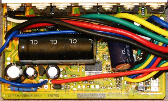
Board ID: EB777XC-080918(350W)

BOTTOM VIEW
EB777.bot.jpg

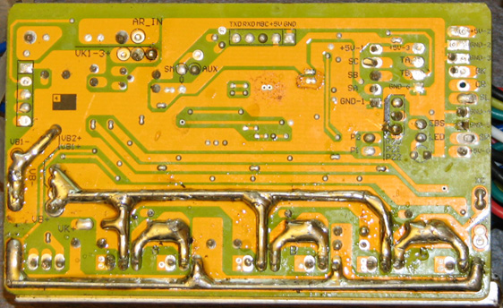
New pads located right side between GND-1 and EBS: P20, P21, P22

The packaging (e.g. the extruded box) did not have anything on it, no label, no nuthin’ except the R_Shunt value. Minus one star; I don’t care that I know what I ordered – I expect proper labeling of product.

Confirmed:
  • Infineon XC846
  • IRLB4030 Qty-6
Reference schematic:
EB206 My other 6FET controllers from eBikes.CA map to this version pretty well.

Upgrades OoB:
  • C1 to 100V 1000uf
  • C2 to 100V 100uf
  • C201 to 100V 220uf
  • R1 = 201 ohms 2W, was Qty-2 (parallel) but is now just Qty-1.
Notes: Dig the cap upgrades – plus one star. Also dig the clear labeling of the Programming Header on both sides of the PCB. A little confused over the change in R1 value though.

MIA:
  • Pins X1, X2, X3 for 3-way Speed Control
  • EBS- and EBS+ replaced with just EBS.
  • According to Ebikes, it is not required to short BK to GND to enable Regen. I can confirm that mine is not shorted. Instead BK and GND go to the EBrake connector (formerly was EBS- and GND).
  • Fwd/Rev, one wire goes to GND-4, while the other to P21 in a new area with three pads, P20, P21, and P22 (located between GND-1 and EBS pads). Could this be the replacement pads for X1 through 3? It sure is painted on the backside like a 3-pin connector. Called eBikes to query but they said they don’t support 3-Way Speed control. Boo hoo ~ minus one star. Must investigate further…
Conclusions:
I am keen to learn if the P20-22 series maps to the X1-3. I won’t know until I give it a twirl, but odds are that someone else out there in the virtual realm already has an answer, yes?

Cheerios, KF
 
Im waiting for Lyen to make some baby 6fets. I would like a 72v 40A. I know they are capeable with 4110 but i dont know why he hasnt built them yet. HIT WINK NUDGE!
 
Maybe you refer to Lyen's 9 fets stealth controller with 4110 (not 6 fets). I think he has last one left.

icecube57 said:
Im waiting for Lyen to make some baby 6fets. I would like a 72v 40A. I know they are capeable with 4110 but i dont know why he hasnt built them yet. HIT WINK NUDGE!
 
Hi,

I have also bought one of these 25a and a 40a.

I used the 25a with a 408 front motor at 48v. Very usable. It goes straight to 25amps and stays there under load which is nice. From reading info on the nine continent website which supply these controllers, they are factory rated at 27 amps and quite capable of speed settings.

I have the same questions about the pads, some one will be selling them with the 3 speed switch, then we could tell where to connect. But its got to be those P pads.

I found the regen good at 48volts. Delivers 6amps engaged.

As for the 40amp, I am running it a 72 volts and the regen is lame, puts back about 2 amps engaged which hardly slows the bike.
Also the 40 amps controller seems to be at about 36amps under load, and I have never seen it at 40 (though it has peaked to 40)

Can anyone tell me can I use my keywin software to change the parameters on this model board?
 
Kiwi said:
Hi,

I have also bought one of these 25a and a 40a.

(snip)

Can anyone tell me can I use my keywin software to change the parameters on this model board?

Kiwi, I haven't tried yet, but my assumption was that this would use the same parameters as the EB806 for the Infineon app (and not the 116).

BTW - do you know if the 25A can run at 72V? I had planned on 74V-nominal for my pair. 8)

Thx, KF
 
kingfish I have a similar board but date stamp on board makes it one month older than yours, came from different source.
but it has x1 x2 and x3 on it.
see pic
can you follow your pin 21 for reverse and tell me where it connects to the chip? and via what smd resistors/caps?
 
Whatever,
What you have denoted in your image as pins 15, 16, & 17, are actually 12, 13, & 14; Pin 1 is at the bottom-left of your chip in that view, and there are 16 pins to a side for the Infineon, so you won’t have pins 16 and 17 on the same side my friend. :)

Incidentally, those traces on your board don’t go where they do on my board; mine are routed from beneath the chip and out towards the right. On your board where you denote X1, 2 & 3 there are six discrete SMDs whereas I have seven. I’m not so convinced we are alike, but I appreciate your kind thoughts :)

Pin 21 = PC-
The schematic I reference at the top of the thread shows where this goes.

Best, KF
 
AW, I thought we had only the "Infineon" (32-pin) and the "116" squarish format. :?

How many varieties of this critter's brain are out there? :shock:
 
kingfish thanks for info on p21 =pc-
I can see it on the schematic, that schematic is 116 chip, your pics show you have infineon chip, the controller you put pics up of is date stamped 2008, its an early version board, if you really want to use speed settings I can map out how to connect it, will take me quite a bit of time to draw it up from the board I have here.
 
Kiwi said:
Yep they can run at 72 volts. you need to change the resister R01 http://endless-sphere.com/forums/viewtopic.php?f=16&t=7361 toa 500 -600ohm, and at least a 2 watt, I blew up a 1 watt, now I put in a 5 watt because I had one.
Hi Kiwi
Thank you for your help; that was quite useful. I think that the suggestions for 72V-nominal will be good enough; the range given is 60 to 90V, and I would operate between 60 to 84V so all is good there. My controllers do not have R6 installed, but I don’t think I need to worry about it since the package is mounted to the aluminum heat sink.

Small question:
I’m at Digikey and there are a few types to choose from. For construction, could you rate best to least-desirable?
  • Metal Film, Metal-Oxide Film, Wirewound, Non-inductive, Wirewound, and Ceramic.
Would it make sense to choose a Temperature coefficient and Tolerance that are low?

Is there any benefit to go with two 330 ohm 2-Watt in series, or a single 680 ohm 5-Watt?

Thanks :)
 
whatever said:
kingfish thanks for info on p21 =pc-
I can see it on the schematic, that schematic is 116 chip, your pics show you have infineon chip, the controller you put pics up of is date stamped 2008, its an early version board, if you really want to use speed settings I can map out how to connect it, will take me quite a bit of time to draw it up from the board I have here.
Whatever:
Dang… When yer right, yer right! My humble apologies; my middle name begins with “N” and ends with “B”. :oops:

I count 20 pins on a side; 40-pins total. I don’t have a spec on this. Also, the image of my pcb top-side is a little washed out where the date is; mine is 20090828 which is a little bit better than 2008, yes?

Maybe I should change my name to “eediot!”
 
Kingfish said:
AW, I thought we had only the "Infineon" (32-pin) and the "116" squarish format. :?

How many varieties of this critter's brain are out there? :shock:
Probably at least a few; most MCUs have at least a handful of versions in different packages, with varying amounts of I/O lines. Sometimes more analog lines, sometimes more digital, sometimes switchable between the two.
 
2009 is more recent, I quite like the older boards though since they still have the infineon chip, the 116 someone on the forum said it was made in house by xie cheng, I have no idea if the 116 is superior chip to the infineon, the boards to seem to change quite a bit from one batch to the next from xie, so I assume each change is for the better. Certainly seems to be more options to vary on the program that works with the 116 chip ( assuming the new program wont load into an infineon chip, but no idea really, haven't done any programming).
I'm drawing up the board I have here, just to help my own understading of the board. I'll post on the forum when done, still working on it, quite a big job to draw it all out.
 
From what I know, there are two distinctly different chips and they each use appropriately distinctive flashing applications: The one marked “Infineon” can only be used with the XC846 chip. Likewise the one marked “116” is for that particular chip (I don’t have the number off the top of my head since I don’t own that varietal). Selecting the proper match between the two is a common problem, and directly associated with flashing errors.

Visually, the XC846 has a rectangular outline whilst the 116 appears square. But that’s just my observation. As Amberwolf said,
“...most MCUs have at least a handful of versions in different packages, with varying amounts of I/O lines...”
I can believe it.
Appreciate your contributions, KF
 
here is the schematic of the speed settings pins etc on a xie controller
speed select x1.jpg
 
kingfish did a couple more diagrams, its starting to make sense.
Circuit is very simple. Pins 15, 16 and 17 are the ones involved for speed selection, each of those pins has exact same simple circuit, off each pin the current can go either via a capactor to gnd or via a resistor to gnd ( when x1,x2 or x3 is selected by grounding)
It couldn't be a simpler circuit!! there are only 2 paths for the current to go down. As far as I know only the 846 chip is used by xie cheng, so your chip should be same one.
It looks complex but once you break it down its very simple circuit, although how its laid out on the board makes it look complex.
speed select mod1.jpg
 
Thanks for that. Very useful. What would we do with out the internet and ES, scratch our heads for along time, make many small fires.

Well, that all makes sense. Unfortunately I have just sold my last controller so don't have one to trace and see if the P pads are the replacements for the X pads.

I will get a few more soon. Anyone keen to flash one and see if that works?
 
psicoticos said:
it's possible, in new controller with P20, P21, P22,
setting the e-brake power?
Hi psicoticos

I believe these pads are for linking to visual indication such as simple LED input with the other leg tied to GND. When you look at the clustering of the pads and the silkscreen outline it seems like a spot for a connector conveniently located next to the Power/Diagnostic LED indicator (should one want this feature).

Traditionally ebrake requires two tasks to enable it: The circuitry must support it (switch or jumper on the PCB), and in the Firmware set (Off, Active Throttle-Brake, Active Throttle/Passive-Freewheel & Brake-Regen).

At present I do not have this controller mounted.
Best, KF
 
Thanks,

I have 2 new infineon controller 350-800w, all have two external wire to enable/disable regen,
the 350w model is eb777xc, i've try to programm this but the keywin programm nothing, idem for 800w (in this moment i dont know the model).eb712xc
I do not use it the 350w model, and I do not care, the problem are ebrake power of 800w controller...I can not program it (I asked if it could be done via hardware)

Thanks
Max

Sorry for my English
 
psicoticos said:
it's possible, in new controller with P20, P21, P22,
setting the e-brake power?

Hi,

P22 to ground will enable regen, no idea what P20 and p21 will do.
I 've got an EB777 (same one as on the first picture of this thread) Controller was in a set with a NC205 motor and a thumb throttle. I am positive about P22, cause i desoldered the bridge and regen was gone, I also desoldered a bridge at P21 but did not detect any difference. CR to ground is Cruise Control enabled (also positive about this one).

(By the way I am new here, was searching for the meaning of P20-22 and did find this thread. I am living in Amsterdam, Holland. I have an Electra Hellbilly with Cute 85 with Ecity KU62 controller or NC205 with EB777 controller both used with thumbthrottle and PAS).

Ronald.
 
P20 and P21 Are the speed settings. Connect P20 to ground for Speed setting one or P21to ground for speed setting 2 or neither for controller default speed.
 
Back
Top