Torque Arm Feedback

geoff57

10 kW
Joined
Apr 25, 2007
Messages
752
Location
England
hi all
I'm starting this thread to help ebikers out there who have hub motors and need torque arms for them advice from all is wanted as I want to make this as compleat as posable.
companys that make arms
axel hole shapes for diffrent motors
size and thickness of arm for a motor at a voltage

all and anything else you can think of wanted

The first thing I have to say is find a lazer cutter to cut out the arms for you if they need to be custom jobs, ask around I am getting a pair for my new build out of 8 mm stainless steel for £15 the shipping would be that as well so I will collect.
 
The main torque arms I see here are the black one from powerridestore.com
and a box type wench. I've seen some custom made ones too. I think the
black one was the only off the shelf one so to speak. There might be more now though.
 
10mm box wrench.

However, there are some instances of these popping out when used unmodified.

to use one propperly, you need to ensure 3 things.

that the sides of the open end of the wrench are flat, so that the nut can sit flat against it.

That the wrench is able to go atleast 2/3 of the way around the axle. you may need to use a file to open up the rounded area in the jaw of the wrench.

That the wrench is held secure to the bike. Under jarring or hard bumps, one held with only hose clamps may be twisted or jarred lose if not held securely. This is true of all thick torque arms,

benefits of the wrench are that it's forged steel, and stronger than the mild steel or stainless steel used in the laser cut arms.

Drawbacks: it looks like a wrench bolted to the side of your bike. can pop out if unmodified
 
I used a wrench as a torque arm, once the sides broke when the axel started to turn it was a dc 200w motor on a 20" rim, some wrenches may work but I would not trust them this is my opinion.
on the way to go for people in the uk I think I have found a good source of custom lazer torque arms in the company I am dealing with I am going to check on postage costs tomorrow
so far they have made test sample cuttings of the axel hole so I know that it fits over the axel and like a glove, I had a quarter moon shape made up to fit in the frame between the axel and the frame. the arms are made of 8mm stainless steel a pair are going to be about £15, the arms are drawn on a cad package then sent to the lazer cutter this means that we can get the arms customised to the cycle it is going on the end user just has to take mesurements the axel can turn round to match the angle of the dropout to the chainstay.
 
OK I bought one of these the 14mmx10mm one and it fits my 36v 500w GM rear motor and the old 1991 Schwinn Sierra it's mounted to. I did NOT use the stock axle nuts supplied with the GM kit as the threads were not square with the face of the nut. So I purcased a good quality nylock/aircraft locknut. Still after a few hundred miles I found them loose. Thus the reason for my purchase of a torque arm. The arm looks and fits quite nice. Someday soon I may even get it installed. Which side should I install it on?

http://cgi.ebay.com/Front-Rear-Electric-Bicycle-BIKE-Torque-Arm-Crystalyte_W0QQitemZ110269780321QQihZ001QQcategoryZ98083QQssPageNameZWDVWQQrdZ1QQcmdZViewItem
 
biohazardman said:
OK I bought one of these the 14mmx10mm one and it fits my 36v 500w GM rear motor and the old 1991 Schwinn Sierra it's mounted to. I did NOT use the stock axle nuts supplied with the GM kit as the threads were not square with the face of the nut. So I purcased a good quality nylock/aircraft locknut. Still after a few hundred miles I found them loose. Thus the reason for my purchase of a torque arm. The arm looks and fits quite nice. Someday soon I may even get it installed. Which side should I install it on?

http://cgi.ebay.com/Front-Rear-Electric-Bicycle-BIKE-Torque-Arm-Crystalyte_W0QQitemZ110269780321QQihZ001QQcategoryZ98083QQssPageNameZWDVWQQrdZ1QQcmdZViewItem

hi they are the arms sold by Hi power cycles check out the thread below
http://endless-sphere.com/forums/viewtopic.php?f=9&t=5285
like most torque arms the arm is fitted to the non-drive side, the main problem you will have is with the power/sensor cable if it comes out of the non-drive side then the connectors have to go through the hole in the arm, this is always a problem with torque arms.
For this reason my motor has had crimp connectors on, the crimping has been done but the housing has not been fitted yet and will not be fitted until the torque arm is on the axel or at least the cable.
 
Kinda figured you would say to mount it on that side as I just got done re-wiring everything for the second time. Pulling out all of the terminals from their plugs and putting them back in again is a pain. Well guess I should be good at it by now. Will wait till I get a 48v battery then I can do it all at once. Thanks


Well I rigged up a 48v battery Lifepo4 an SLA combo and installed the 48v controller as I fried my 36v regen. Lots more torque so it's good that I put the arm on. The nuts have not worked loose at all since. That was about 400miles or so back.

torquearmschwinn.jpg
 
Is this just a problem on aluminum forks or?
I have been overvolting an amped kit and it has quite a bit of torque, I dont want to ruin my forks. I am using chromemoly forks should buy one of these or?
 
turoczi said:
Is this just a problem on aluminum forks or?
I have been overvolting an amped kit and it has quite a bit of torque, I dont want to ruin my forks. I am using chromemoly forks should buy one of these or?
hi
mos will say that torque arms should be used if you can the dropouts were not designed for the rotational spreading force the flats of the axel put on them if the nuts get lose.
Do the math price one maybe two torque arms cost if you are unlucky $30 (you will probably find cheaper) add that to the looks on your bike the think of the alternative no torque arms nuts comes lose axel spins, this causes damage to the the axel wire and probable short circut blown hall sensors in the motor the controller will probably have several blown fets both are difficult to replace, plus there will be te time off road and I don't mean on a dirt track and posable humiliation from the pedal bregade if this happens in town, in turns of money alot :( so an arm is a good idea and should be told when buying what arm to have eg supply a list of what arms to use in what situation voltage, wheel size, terain then give arms recomended for the setup, with recomended material eg stainless steel. Lastly a cad file should be made availible for the buyer to give to a lazer cutter if that is the route they take with arms with the dropouts at diffrent angles to the chain stay, in the common cad formats .
I will be posting one soon if anyone can tell me the axel sizes the have I can add them in I will do 12 14 with 10 flats if anyone has any diffrent please post, also dropout to chainstay angle, distance from bottom of chainstay to axel centre (I will show how to take these mesurments in picture form on a future post ) finely if you have a camra that can take good closeups remove the nut and washers from the side the wires don't go in and take a closeup see the pictures in my thread on my kmx mk2 viper build where I have just posted just such closups I would like some feedback on my "quarter moon" fillit to transfer the weight of the user to the frame correctly .
 
ok Guys
I said I'd design an arm from scratch, well I've done it.
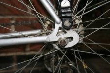
I took a picture of the dropout the arm will fit on (it is one of my friends pedal cycles).
torque arm design web2.jpg
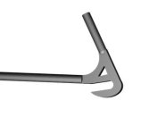
I took all mesurments and put them into my cad package to make a dropout in the computer for the thread it was not needed to design the arm.
torque arm design web4.jpg
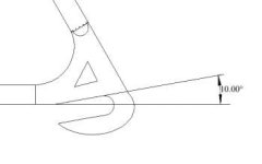
the vital information needed is the angle between the dropout and the chainstay see below
torque arm design web3.jpg
in the next post I will finish show the design and provide pictures from the cad package of how they fit together.

I have been told dxf files are too big to post but dwg files can be posted so the cad file will be posted as well.
 
Don't think so. The ones on my MTB and BMX are different and I don't even have to measure to tell.

LOL @ that avatar, BTW. I wouldn't have thought Gaara would have been incapacitated by brainfreeze. :wink:
 
turoczi said:
Is there a standard angle for front forks? I came up with - 15 deg

There are certain limits beyond which handling become problematic. Choppers and track bikes are extremes. By fork angle are you referring to the relative angle of the head tube of the frame?
Generally the fork caster or trail are all close among given wheel sizes.

Slack sloping head tubes give relaxed handling. They're best combined with upright seating and longer wheel base bikes. Shorter wheelbase and steeper angles are more for track or criterium racing. Road racing angles are usually steeper than tourers.

If you're talking about the angle of the fork end where the axle goes in relation to a straight fork leg/blade that angle is tied to you trail measurement and angle at which the steerer tube is attached to the fork crown.

Many bike manufacturers have frame geometry diagrams on their web sites.
 
hi all
I'm concentrating on rear hub motors at the moment due to working out my own rear hub motor torque arm, not to be said to forget about people who have front wheel motors below is a picture of a closeup of a front fork from the side.

as you can see the angle between the flats of the dropout and the fork is 0 degrees this is fairly common with straight forks, with curved forks you have to take onto account the point at which the arm will be fixed to the fork I will talk about this later.
 
hi all
ok here is the second part of the example of creating a torque arm from scratch for a rear dropout .
the file that contains all the information is incuded
torque arm design web6.jpg
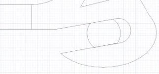
in the picture above the grid is 1mm spacing the hight of rise of the axel is only about 3mm between the bottom of the chainstay and the top left corner of the axel as seen from this side view the end results are shown in 3D on the model page of the file on the profile1 page at the top is the torque arm for the dropout below that are the 3 parts that make it a rectangular "arm" 20mm deep with a hole at one end, a 30mm circle with a axel hole in the centre and a 20mm by 30mm block.

the way to make an arm is to highlight the 30mm circle and rotate it to match the angle of the chainstay to the flats of the dropout,then move the circle to the end of the "arm" and move up to the correct distance , fill in the gap with the 20mm by 30mm block, print out on paper cutout and hold up to your dropouts to see if they fit.
torque arm design web5.jpg
above is a picture of the arm in the cad program .
 
Hiya.. With the tire rotating forward.. wouldnt it make more sense to attach the torque bar on the upper bar?
It is hard to get a solid upward connection the way you drew it up. But this way you can use a simple metal strap and the tension is alwas PULLING on the strap instead of pushing..
The way most people use it is the same way you drew it up geoff.. But that method is using the strap as a pushing point, so the weakest link which is the strap usually will bend. by putting the strap as I did in the picture there is no weak spot
rotationxb3.jpg
 

Attachments

  • rotation.JPG
    67 KB · Views: 1,884
turoczi said:
Hiya.. With the tire rotating forward.. wouldnt it make more sense to attach the torque bar on the upper bar?
It is hard to get a solid upward connection the way you drew it up. But this way you can use a simple metal strap and the tension is alwas PULLING on the strap instead of pushing..
The way most people use it is the same way you drew it up geoff.. But that method is using the strap as a pushing point, so the weakest link which is the strap usually will bend. by putting the strap as I did in the picture there is no weak spot
hi all
first have a look at these pictures
torque arm design web7.jpg

I agree with you that an arm 5mm or more from the chainstay(chainstay lower fork seat stay upper fork) and if on turning clockwise the arm would miss the chainstay then the design has a flaw it would not so much bend as crumple. In my design the chainstay and the arm overlap a bit the gap should be filled in to make for a better design I use thin aluminium and inner tube offcuts.
the subject of the best sort of clamp or strap to use will be discused in later posts this is one reason I have not put one on the design.

On consultation with a cycle expert who confermed my thoughs what you sudgest although looks and seems logical, so we have choices do we use compresion or tension and do we use the chainstay or the seatstay. I will address the second first, the chainstay is a lot stronger than the seatstay although they may be the same size, so it is advisable to use the chainstay. As for the other choice compression or tension with the first the method most use (though should get rid of the gap) the force is acting on the arm pushing it toward the chainstay this is imho the best method as the load is spread over the largest area, if there is a gap then there could be problems the strap may crumple and the dropout would be dammaged though the axel would probably not end up spinning. With the tension method there is a lot mor danger the bolt can shear off I have had friends who have done the reverse with brakes and ended in hospital, overall it is best to go for the way I have been showing it the strap should not do the work the arm against the frame should we have to have fillits made for arms that are not close to the frame.
 
I have a 30 year old "stroker" bmx in my garage (any old skoolers remember the stroker?)

I was looking at it and noticed the old coaster brake setup. I took a look at it and after 30 years of riding it the paper thin strap has no tears, rips, stretches etc.

My big thing when I was a kid was to haul butt down the hill then hit the brakes and skiddd to a stop. Although I was a lot lighter back then 8) the coaster brake never failed (coaster brake rotation is reverse of e-hub).

I say "if it aint broke, dont fix it" soo when i get my new and "free" rear kit from amped ill be putting on like in my picture above lol..
:mrgreen:

coasterbrakepa8.jpg
 
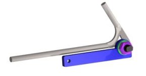
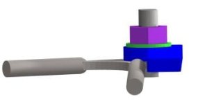
Hi all! Let me introduce myself. My name is Danny Ray, I own Ampedbikes. I have been doing this as a hobby that I love for a few years now, designing and redesiging quality kits. I have had the last batch custom made to my specifications and I hope everyone likes the new kit design(front and rear), its very heavy duty, waterproof, lightweight and will last a lifetime. I am able to keep costs to a minimum on my kits because I do this in my leisure time. If anyone wants to see anythign else added to my kits please dont hesitate to email me and I WILL do it!

I have been following this post but had to wait untl my patent went through to post our designs.

I have 12 bikes in my shop and discovered that the dropouts are at different angles front and rear on all of them!

So after a couple hours sitting in front of my computer I came up with what I believe is a very good design.
I thought it was good enough to patent it. Here is our first pantent info.
Our patent pending #61083952

piece.JPG


Fully adjustable and strong as an OX!
1s.jpg

2s.jpg


5s.jpg

adjustable to any angle


7s.jpg

The washer locks everything together


8s.jpg

The nut does the rest of this, making sure everything is tight

9.jpg


We are still designing a nice adjustable strap..


Thank you all for your support!.

Ampedbikes was an almost non profit hobby for a few years. I used it to clear my head after dealing with architects and designers all day long from my main business http://www.drayconstruction.com

We will continue to provide high quality kits for the best prices around.. Or at least until we start losing money on it !! :p :p

Thanks guys!

Danny L. Ray II
http://www.ampedbikes.com
http://www.drayconstruction.com
 
Yeah, that's awesome thinking... nice work! Please do let us know pricing and availability when you can.
 
Will do and thanks for your generous replies!!!!!!

I have 1,000 pieces on order already but I am thinking of possibly adding one more small cog offset by 1 deg so that some odd offsets get a perfect fit.

Danny Ray
http://www.ampedbikes.com
 
Back
Top