bobc
10 kW
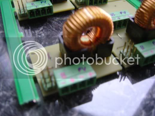
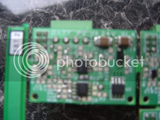
Just a quick note about a project I'm working on; it's a solar charger for a 24V lead acid battery. It's a small (and I mean small - 25mmx40mm) PCB which runs from a 20V PV array - the sort you'd use to charge a 12V battery with a shunt regulator.
To do the maximum power point thing, it has a AVR ATtiny5 microprocessor on it - this thing has just 6 legs but that's more than enough to measure array amps and volts and provide a control output to set the array voltage.
Progress to date on 1st pass circuit: the "float charge" control works beautifully (controls output to 28V max) and the "bulk charge" controller, where it does its maximum power point tracking thing, also works beautifully, controlling the array output voltage to anything you want (provided it's lower than the array open circuit voltage of course...).
We got the maximum power point tracking software going today - brilliant fun, you can see the array volts stepping up and down as it searches for the maximum power point (I use the perturb & observe or hill climbing algorithm) but there's a fair bit of optimisation to be done in that area still.
So I've just sent off for the 2nd generation PCBs (with errors corrected and redundant elements removed) - they'll be back in 10 days.
I've done the circuit for my brother's gate automation business, but it looks as though they will be commercially available from a firm in Ashton - we'll see.
On the prototype the battery supplies about 2mA to the circuit, just in the battery voltage feedback path - I can reduce this by a factor of 10 or so in the next spin.
The circuit should get 10 to 30% more juice out of a given panel, so reduced PV panel cost should pay for it. It just uses low cost generic parts, the tiny5 is just 22p.....