Ultralight Solar Charge controller

walls99

100 W
Joined
Mar 11, 2009
Messages
114
Location
UK
New project for a friend building a solar RC plane -> Ultralight Solar Charge controller:
- Solar input: 5V to 20V
- MPPT: P&O
- Output: 1 to 3S Lipo battery
- Cell Under/Over voltage detection
- weight: 5-6gr
- target efficiency 95% at 4A output

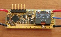
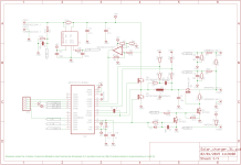
The design is based on MCP19111 which integrates an analog-based PWM controller and a PIC Micro-controller, the output voltage is fully programmable in fine steps, so the plan is to "perturbate" the output voltage and "observe" the input power to maximize it.

Basic DC/DC mode is already working and it's looking like this:
IMG_2716s.JPG
 
The version 2 is finished and working, see picture below:

file.php
 

Attachments

  • IMG_3446_s.jpg
    IMG_3446_s.jpg
    123.3 KB · Views: 2,031
Here is a brief description of how this works:
- The MAX4372 is a current sense amplifier used to measure the solar input current (I_IN).
- The solar input voltage (V_IN) and I_IN are regularly sampled at ~100Hz to calculate the solar input power (P_IN)
- The MCP6401 is a rail-to-rail op amps used to invert and rescale V_IN range from 6V-14V to 3.6V-0V, so it can serve as voltage feedback for the MCP19111 voltage control loop. This effectively allows the MCP1911 to control the output current to regulate the input voltage instead of the output, hence controlling the solar input power.
- The power stage (Q8/Q9/L2/C9) is "standard" and the current sensing circuit used voltage dividers to allow extended output voltage above the MCP19111 3.6V limit.
- Q3/Q2 are there to prevent current flowing back from the battery into the charger circuit. Q1 is an optional protection circuit for Q9 when using the ICD which can paused the MCP19111 with LDRV high.
- The Maximum Power Point Tracking is done using the Perturb and Observe method by changing the solar input voltage and maximizing the solar input power.
- The charger stops when any of the cell voltage goes above a pre-set level. There is no charge current control because the solar input power is too low in my application to generate charge current above the battery limit but this could be done by limiting the input power in the SW.
 
any updates on this project or controller..
very good, would like to buy 2
 
Can one submit the schematic as is to a circuit provider /maker or does it have to be in a certain format?

If it has to be in a certain format can someone provide it?

Thanks.
 
myzter said:
any updates on this project or controller..
very good, would like to buy 2

The controller version 2 with the minor mod is my final version for now. The Solar RC plane, it was designed for, is still under construction. I'm not planning to build/sell those but feel free to re-use the schematics see above and PM me if you need the firmware.
 
A few of these could be ideal for my solar mulirotor project. Thank you for your work! If you are willing to make a batch of PCB's and sell them with margin, I bet I wouldn't be the only person buying them.
 
I have a dozen of these.... they are great for charging Ebikes >30V from almost any panel!

http://www.ebay.com.au/itm/DC-DC-600W-10-60V-to-12-80V-Boost-Converter-Step-up-Module-Car-Power-Supply-GA-/181754872831?hash=item2a516f43ff

have a dozen of these too measure what goes in and out
http://www.ebay.com.au/itm/LCD-Digital-Watt-meter-Ammeter-Power-Analyzer-Voltage-Watt-Meter-60V-100A-/221597793708?hash=item339841fdac
 
these a little cheaper but cant be used without a current limited source (like a panel)
or they will melt if you're not very careful (ask how i know!)
https://www.youtube.com/watch?v=dcU8Xz4Zh7w
 
Back
Top