Are generic Chinese controllers and throttles non-adjustable?

Barncat

1 kW
Joined
Oct 26, 2020
Messages
364
I assume the answer is yes.

I have a 5 wire Hall sensor throttle with V indicator and a 60v 55A controller. Both are ostensibly made well.

The annoying thing is the instant voltage is applied from a standing start too much motor torque is generated, even with the most delicate possible twist, making launches somewhat jerky and unpredictable. This is bad for SO many reasons and makes precise performance riding very difficult.

The V curve should be parabolic not so linear, in layman's terms. My bad for not buying an expensive controller- or is harsh launch a more universal problem?
 
Inexpensive generic controllers are usually modified sine wave (trapazoid wave) and are generally not serviceable much. If you want smooth starting a sine wave will give you more of that depending on your motor / controller setup. Bluetooth controllers are more programmable, and yes, more expensive.

The throttles are also generally not adjustable, although when the SS49E Hall sensors have burned out in a few of mine, I have replaced them, so they are somewhat serviceable.

There is lots of info on sine wave controllers on ES. Start here and look around.

https://endless-sphere.com/forums/viewtopic.php?t=98534

:D :bolt:
 
Read through the link, thanks, and will invariably do more study than I've already done. Have rudimentary knowledge of trap, sine and foc.

To be more specific- I have a standard issue ebay component setup on the Mongoose girder build referenced elsewhere, with a 3000w "Kunray etc" inrunner motor. 13T front sprocket, 80T rear and 20" tire.

Actually, everything other than the harsh potentially spastic launch works great. This is on a 20s battery btw. Whole setup is pretty quiet even with the 25H chain, but I had a nasty inside chain derailment which jammed the wheel solid due to a large extent on the issue described. I'll be adding a couple polycarbonate guide discs to either side of the rear sprocket. Had that happened at 45mph........ I'm here to say those chains have plenty of tensile strength but are WAY easy to throw even with careful alignment.
 
My further musings:

1) I could avail myself to the 3 speed feature on the controller and add a rocker switch to the bars... sort of a half-assed clutch. Launch in low and immediately switch to hi. Initial plan was who needs lo/medium settings...

2) I could go up a tooth on the front sprocket. That would also likely get me to 50mph.
 
TC- thanks for that very detailed link. Pretty sure I scanned some of that weeks ago out of curiosity. Will study further.

It may be unclear from my previous posts but I do not believe any of my equipment is malfunctioning in any way. I suspect it's the baked in EE design and am curious if other guys with this stuff notice a similar issue. It's not horrible but it's certainly noticeable, particularly if you must stop and start a lot. I'm also over volting the controller.
 
TC- coincidentally I seem to have hit the nail on the head in my original post re parabolic vs linear voltage which is exactly what you plotted for pot throttles at the end of your instructional write up. I was big into HO scale slot cars in my early teens and am craving that smooth ramp up of power delivery, yet with a soft predictable launch.

I've tuned about 20 cafe racers and the toughest band to get right for ICE stuff is also right off a closed to 1/8 throttle. If you ride the mt twisties like I do smooth power delivery is essential. No different for an ebike...
 
There have been things like the Throttle Tamer by Zombiess designed for just the purpose of doing what you want...but the TT isn't made anymore, and I dont' think he ever published the code and schematic, but it's a relatively simple device, so if you are inclined and know about MCUs (arduino, etc) it is possible to create a "mapping" device that takes your actual throttle input and applies some math to it, and then outputs a different curve to your controller. I don't know how to do this in any detail, and probably couldn't do it since I R Not A Programmer :( but I'd bet there are quite a few here on ES that could throw this kind of thing together in their sleep. ;)

There are also devices like the Cycle Analyst v3 which can help you adjust the throttle voltage that reaches the controller to better match what the controller itself uses, so you don't have "gaps" in the response...but it doesn't change the *way* the controller responds, and it doesnt' have any "curves" to select from. It just helps you better match the throttle's active output movement range to the controller's active voltage input range.

There *are* a number of controllers out there that do let you program the throttle response...but generally doesn't include the "generic" controllers.


Throttles themselves are not programmable, though there have been a couple threads about developing one that at least had a handful of switchable curves. (whcih could easily be done with an arduino, atttiny, pic, etc, that would fit in some of the larger throttle housings).
 
Barncat said:
I seem to have hit the nail on the head in my original post re parabolic vs linear voltage which is exactly what you plotted for pot throttles at the end of your instructional write up.

The output difference took me quite by surprise. But certainly explains why POT throttle riders like how their throttles "feel".

Just being a novice in electronics... another possibility might be to use a cable throttle with a throttle box. (like the earlier Surrons)
And make a "profile" CAM on the cable actuation between the two, to get the smooth ramp desired. (small movement early, with more at the middle/end of twist.)
All purely mechanical as far as the modification of the output curve. :!:
 
I didn't really think there were any adjustment/program capabilities on these components.

Not sure I'll veer off into arduino land yet amberwolf as I like to keep things simple but appreciate the suggestions.

I think the pot throttle approach is what I'm looking for if I decide I can't live with the basic Hall twister.

However, I'm not clear on exactly what's happening at the instant the controller sees trigger voltage to kick the motor on (my controller spec says the range is 1.1- 3.7V btw...). Isn't an instantaneous hit going to by definition cause a jerky wheelie start as you refer to it TC in your #1 mod? Or is it the controllers job to spread that hit over some microseconds, which is where programming capability comes in? The whole situation is amplified by the inherent "instant" torque of electric motors so that's a bit of a downside re this issue.
 
Barncat said:
I think the pot throttle approach is what I'm looking for if I decide I can't live with the basic Hall twister.
Remember a pot throttle will need some extra resistors on the ground and the 5v line to give it's full mechanical range of control (so that it operates over the same voltage range as a hall throttle would, for those controllers with no way to adjust the input range).

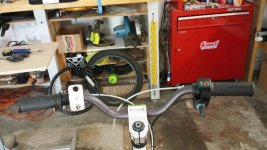
A cable-operated hall throttle (COT) will, as Tommycat notes, be adjustable mechanically if necessary, changning the amount of cable pulled by the grip vs the amount of rotation of the COT for that cable pull, simply by changinng the input pulley size on the COT itself. To see basically how these look, you can go here:
https://endless-sphere.com/forums/viewtopic.php?f=2&t=105460
where I use a COT and a brake lever to get proportional regen (with a controller that has taht kind of input; most don't). I also use a separate COT on an ATV thumb throttle (cuz they're the only metal thumb throttles I can find...and the palstic ones break off when I hit bumps and am at WOT :( ).

They also make potentiometer versions of the COTs, but I haven't used those yet. These can actually be built relatively easily, vs building a hall COT. (at some point I'm probably going to convert a hall COT into a pot COT for a special purpose test).

However, I'm not clear on exactly what's happening at the instant the controller sees trigger voltage to kick the motor on (my controller spec says the range is 1.1- 3.7V btw...). Isn't an instantaneous hit going to by definition cause a jerky wheelie start as you refer to it TC in your #1 mod? Or is it the controllers job to spread that hit over some microseconds, which is where programming capability comes in?
What any controller *should* do is that as soon as the voltage on it's input reaches it's threshold, it should just barely begin applying power to the motor. As you increase throttle from there, it will continue to increase power to the motor. So there is no "hit", exactly.

How the controller responds from there is where you see the problem with sudden bursts of power with only a little throttle, or with one that gradually does so.

Some controllers also have a "soft start" which responds slowly to the initial (or any) change in throttle, and the rider may keep increasing throttle trying to get a response out of it and then when the controller does respond, it has already been told to output more (often much more) than minimal throttle...and with a higher torque setup, that can be disturbing.

Any controller that uses a "current throttle" or "torque throttle" method (generally FOC controllers do this) will be much more controllable than those using a simple "voltage throttle" or "PWM throttle" method. It doesn't have anything to do with the actual throttle itself, but just the method the controller uses of modulating power to the motor.

A hall throttle itself *also* can vary in how it outputs voltage from the point it begins to do so in it's motion range, up to the point it ceases to increase voltage output. Some of them are not linear, some are, and some are...different, wonky curves, due to the way they are mechanically built inside where the magnets are placed relative to the hall sensor, and how they are moved around by the throttle grip or thumb tab / lever / etc., and how the magnets are magnetized, and which hall sensor they used. And they vary a fair bit on how mcuh you have to move them before they begin outputting anything at all, and how far you can continue to move them without increasing voltage anymore once youv'e hit WOT.

A pot throttle still has the last issue, but there's really only two ways they "curve" the voltage output: linear, and logarithmic, depending on which type of pot they used. (and if you want one, but have the other, you can change the pot out).
 
Amberwolf- thanks for the extensive info.

I wasn't really aware that there was much difference between hall throttles. I don't suppose any of them publish detailed specs... Will research.

Looks like the pot throttles are either Magura or Domino intended more for emotorcycles. I'd prefer to avoid messing with cables and cams and various DIY stuff but from what I see there are no pots that are just 75 degree or so rotation, so there are no direct drive solutions.

You'd think manufacturers would have this all sorted by now but I guess not for low buck componentry. I'll hook up the 3 speed switch and try that approach. Bigger problem is keeping that chain on!!
 
Well said Amberwolf! (where's that like button?)

Just wanted to say that some have reported that the #1 mod that removes the dead zone at the beginning of the twist, resulted in a smoother start. Not sure why but perhaps it allows taking advantage of the very slight voltage curve hesitation at the start of the hall sensor actuation.
 
Tcat- I saw from your #1 mod that the front end dead band could be reduced as desired but still didn't see how that would reduce the "wheelie" start- (which i am getting, front wheel 3" off the ground...) The motor still switches from off to on at some very finite point in time. So it's perhaps how the controller reacts to that sudden event.

Basically what's required is some sort of electronic shock absorber. It's very rough on the power transmission parts...
 
Barncat said:
Tcat- I saw from your #1 mod that the front end dead band could be reduced as desired but still didn't see how that would reduce the "wheelie" start- (which i am getting, front wheel 3" off the ground...) The motor still switches from off to on at some very finite point in time. So it's perhaps how the controller reacts to that sudden event.
There shouldn't *be* a sudden event, is the issue. ;)

The controller should respond to the initial voltage at it's lower limit with just a tiny bit of current to the motor.

What you should do before proceeding further is to setup a voltmeter on your controller's throttle signal input, so red lead to signal and black to ground. Setup the powered wheel offground so you can test this without riding.

Slowly move the throttle and watch the voltage reading.

Please note down *exactly* what happens, at what voltage reading, as you very very slowly move the throttle from zero to just past where the motor begins operating.

This will help us help you find the best solution to your problem, because right now it's not totally certain where the problem actually lies. ;)
 
Barncat said:
I wasn't really aware that there was much difference between hall throttles. I don't suppose any of them publish detailed specs...
Not much of a chance of that. :lol: And they change how they make things, or at least what parts are used, without notice, at any time, so any info you do find only applies to the one they actually tested and published at that second in time. :/

FWIW, I have yet to find any two of my hall throttles, even the ones that look exactly alike, to operate quite the same as each other. This was a PITA on my SB Cruiser trike when I started using 2WD (one motor on either side of the rear end), as I couldn't set them up for exactly the same response. Thankfully it iddn't take me long to just "learn" to make them work the same, because I iddn't want to do all that resistor-tuning, either. ;) Nowadays I use just one signal out of the Cycle Analyst to run both controllers, so it doesn't matter...but it was handy to have separate control and at some point I'll have that as an option again...someday when I get around to it. :oops:

Looks like the pot throttles are either Magura or Domino intended more for emotorcycles.
Thankfully it makes no difference what it was "intended" for ;) --they work just fine for controlling anything that uses a variable voltage on it's throttle input (as long as you add the "top" and "bottom" resistors to scale them to your actual controller's input range vs supply voltage, or use a Cycle Analyst to do this for you). I have a Magura that's used with a Kepler Friction drive, for instance....
 
Agreed it's time to take some measurements.

For what these throttles cost I might buy a couple more and swap them out for comparison. I was not anticipating problems.... not into the cost and hassle of resistor mods of the high end pot units at present.

I'm still sidelined right out if the gate from that chain problem. Anything breaks and it's a #×$@ week for parts to arrive...

Thanks guys for clarifying the issues.
 
Barncat said:
For what these throttles cost I might buy a couple more and swap them out for comparison. I was not anticipating problems.... not into the cost and hassle of resistor mods of the high end pot units at present.
Cost of the mods is negligible (nothing but your time, if you have old electronics you can take parts out of, that happen to have the right resistors for.) Hassle...there is some, but since it's just adding a resistor in series with the ground and +V lines, it's not much work to do since you usually have to modify the wire ends to add whatever connector you're using to them anyway, or to splice them directly into your wiring if you are not using connectors. ;) Calculating out what the resistor values need to be vs the resistance of the pot itself vs the voltage range the controller needs to see, that's a bit more hassle. (though you can actually just use two pots instead of two resistors, wiring only the middle leg and one end leg, leaving other open, to make it easily adjustable...costs a tiny bit more but means no math. ;) ).


I'm still sidelined right out if the gate from that chain problem. Anything breaks and it's a #×$@ week for parts to arrive...
What exactly is this "chain problem"?

EDIT: I found your other thread
https://endless-sphere.com/forums/viewtopic.php?f=6&t=109568
about a bike of the same name, so presumably it's that one?
So I moved my response to the stuff about the chain issue over there:
https://endless-sphere.com/forums/viewtopic.php?f=6&t=109568&p=1615794#p1615794
This bike, right?
file.php
 
Yep that's the bike. Will discuss chain on other thread. I described the problem above in this thread. Of course Fedex showed up an hour ago with a ripped empty envelope that was supposed to contain my replacement 25H chain................

I wired up an SPDT toggle to activate the controller 3 speed function and did some very subtle eyeball and by ear tests of throttle roll-ons with unloaded motor. Lo speed is about 30% output of hi, so I'm pretty confident I can solve the launch issue that way. Bear in mind I also stated above I'm putting up to 84v thru a 60v controller. All components seem to be working fine.
 
As a follow-up, the three speed switch makes a standing start launch just fine, and once you're rolling you can of course instantly switch to either higher range. I suspect that that approach is what the controller designers intended, and I made the problem more pronounced by over volting...

The polycarbonate guide plates on the rear sprocket also work well. So now I can get back to making final build refinements.
 
If you wanted to complicate it a bit ;) you could setup an automated rolling-wheel activated switchover from the low mode to whatever mode you normally use is. :)
 
amberwolf said:
If you wanted to complicate it a bit ;) you could setup an automated rolling-wheel activated switchover from the low mode to whatever mode you normally use is. :)

An electrified automatic transmission? Tell me more! :p

:D :bolt:
 
I cant' think of a super-simple way to kluge a sensor.

The simplest way I can think of in 30 seconds is to take pulses from the wheel speedometer (or if it's a DD hubmotor in the wheel, one of the hall sensors), and then integrate those with an op-amp into a voltage, which once above a trigger point causes a transistor to connect or disconnect the wires to the mode switch as needed to change from the low speed to the high speed mode.

When the wheel speed drops below that same point, the circuit would then switch back to the low speed mode.

Circuit itself would fit in the space of most poeple's last pinky finger segment, even if "deadbug"-wired using DIP parts.
 
Or you can just use your thumb, that marvelous appendage that separates us from the lesser mammals :)
 

Attachments

  • 20210205_112536_compress92.jpg
    20210205_112536_compress92.jpg
    324.7 KB · Views: 785
What, you want us to leave something simple and manual? How are we supposed to overcomplicate things to death like that? ;)
 
Back
Top