add anti theft alarm line to controller

Sparfuchs

1 kW
Joined
Nov 22, 2020
Messages
305
Hello EV friend,
i've bought a mxus 3k turbo and a sabvoton 72150 controller WITHOUT a anti theft alarm line but would like to use my anti theft system on my e bike. Is there a way to add a alarm line to the controller or is there another solution to use my system ?
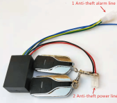
The connections of the alarm system are:
1.anti-theft alarm line
2.anti-theft power line

Red: positive wire
Black: negative wire

Brown: Motor wire
Blue: Controller signal line
Orange: lock output line

Thanks a lot for your help
best regards
Sparfuchs

Screenshot (22).png
 
What does the alarm line on the controller need to do? Is it an input? An output? What kind of signal? What voltage range?

You need to know all those things before you can add one. (or to know if you even need to)
 
I have been playing around with controller boards a lot recently and discovered that one of the alarm wires connects to Vcc (input), as does the electronic ignition/power switch.

I think by applying a 5v current to the Vcc will shut off the controller.

I know it's not a full answer but at least should get you started. I will reply with a bit more info when I have a controller circuit board in front of me.

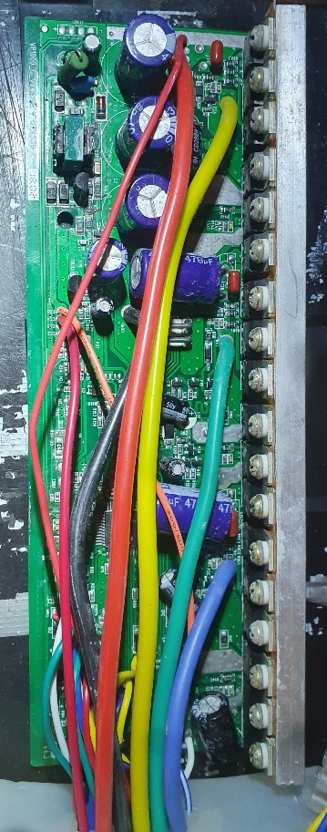
In the pic below, the orange and red wires to Vcc pins are for ignition and alarm.

Sent from my SM-G970F using Tapatalk


3d337b0711c1dd58c1474883c538b571.jpg
 
amberwolf said:
What does the alarm line on the controller need to do? Is it an input? An output? What kind of signal? What voltage range?

You need to know all those things before you can add one. (or to know if you even need to)

Thanks for your reply amberwolf,
that's what i tried to find out but wasn't able to. At the sabvoton infos they just show how to wire it but not what exactly it does.
Does someone know what has to happen usually to trigger the alarm ? Is it when someone pushes the bike and moves the motor or how does the bike "know" that someone tries to steal it ?
 
jamiejackherer said:
I have been playing around with controller boards a lot recently and discovered that one of the alarm wires connects to Vcc (input), as does the electronic ignition/power switch.

I think by applying a 5v current to the Vcc will shut off the controller.

I know it's not a full answer but at least should get you started. I will reply with a bit more info when I have a controller circuit board in front of me.

In the pic below, the orange and red wires to Vcc pins are for ignition and alarm.

Sent from my SM-G970F using Tapatalk


3d337b0711c1dd58c1474883c538b571.jpg

Thanks a lot for your reply and your effort jamiejackherer,
i could try to connect the alarm line to the ignition line and see what happens. But i wonder how the alarm gets triggered that way ? The thief doesn't have a key to do something to the ignition line. Or does it trigger if someone short circuits the lock ?
btw. what does Vcc mean or stand for ?
 
Another additional question i have is if there is a way to block the hubmotor so no one can push the bike ? I've read something like "electric lock" but didn't find a topic that explains how that works ? A explanation or a link to infos would be great. Thanks
 
Not sure about your controller but Adaptto's antitheft function was something that had to be manually enabled-- and disabled with a PIN. It just used power to prevent the motor from turning. Since it only detects Hall switching it had a tendency to rock back and forth, once I came back to my bike (locked + antitheft) to find the motor quite hot, while it rocked itself back and forth against a bike rack. I'm running an ASI controller now and its antitheft function is similar but more advanced-- it energizes the phases with low current and uses that to detect the precise position of the wheel, so it makes a buzzing sound the whole time it's engaged and smoothly returns to the exact position it was enabled at.

In both cases this is a feature of the controller. If the controller doesn't do it by itself, it would be very difficult to design a peripheral to do it (impossible if your controller doesn't support reverse)

Vcc = Common collector voltage. E.g. if you have a harness of a bunch of 5v sensors, the shared +5v signal line is "Vcc".
 
jamiejackherer said:
I have been playing around with controller boards a lot recently and discovered that one of the alarm wires connects to Vcc (input), as does the electronic ignition/power switch.

I think by applying a 5v current to the Vcc will shut off the controller.
Some basic voltage/circuit analysis (made with some assumptions based on controllers I've dealt with; yours may be significantly different; without a schematic of your controller I can't know):

If by Vcc you mean the battery positive input to the controller, then applying a 5v (voltage, not current, current is in A (amps), just to be clear) to it would, unless the battery is first disconnected, probably destroy the thing supplying the 5v, as the much higher battery voltage would force currents to flow inside the 5v supply or switching device that it's not designed for, unless it can sink more current than the battery can source, in which case it will short out the battery itself, which would indeed shut off the controller...but not by shutting the controller itself off. ;)

If the battery isn't connected, then the 5v won't be hurt, but it would also not be necessary to apply 5v to it to shut off the controller, because the controller wouldn't have battery voltage to it to run it anyway.

If by Vcc you mean the keyswitch / ignition / doorlock / etc wire (the one that supplies battery voltage to run the LVPS in the controller that makes the 12v and 5v for the controller brain and gate drives to run from), applying 5v to that (without the battery connected) would typically do nothing different than not having the battery connected to it (which means, it would still leave the controller turned off just like if you didn't connect the 5v). But if you did have the 5v connected there and then accidentally (or otherwise) turned on the bike's switch that provides battery voltage to that point, the situation previously described then occurs, damaging either the 5v source or the battery or the wiring between them, etc.

If by Vcc you mean something entirely different, you'll need to either show the circuit schematic or describe it sufficiently to figure out what would be happening.
 
Sparfuchs said:
that's what i tried to find out but wasn't able to. At the sabvoton infos they just show how to wire it but not what exactly it does.
Does someone know what has to happen usually to trigger the alarm ? Is it when someone pushes the bike and moves the motor or how does the bike "know" that someone tries to steal it ?
Depends on the specific alarm.

Do you have a link to the page you bought the alarm from? There might be information there that would help us help you find the solution (there might not...).

If you know what voltage the alarm is powered by, you can power it with that, and then use a voltmeter to check the other wires for signals, using the black meter lead on the battery negative, and set the meter to 200vdc, and use the red lead to see what voltage, if any, exists on the other alarm device wires first when it is not activated, and then when it is activated.


Some of the alarms are simply powered by the bike battery, and then they do whatever they do. Some (probably most) detect motion of the bike (like bumping it, moving it, etc). Some detect rolling of the bike using a separate wheelspeed sensor.

What they do after they're triggered depends on the alarm. I expect most just flash lights and make sounds. Some, if they are made for a specific controller and wired to that one correctly, could potentially tell the controller it's being stolen and to lock up the motor wheel (if it's a DD hubmotor), though I havent' seen one like that yet, it's certainly possible to do it if both alarm and controller were designed to do it. (but the alarm wouldn't work on any other controller that wasn't designed the same way).

An alarm could be (don't know if any are) designed in a generic way to turn the controller on (short the keyswitch/ignition/doorlock wire to battery positive) and engage the ebrake for regen braking to make it harder to ride away with...but that depends on the controller having regen braking designed into it and enabled, and of a sufficient type and level to be useful for this, *and* the motor being a DD (or other nonfreewheeling) hubmotor in the wheel, or having no freewheel between the motor and wheel if it's not in the wheel.
 
Sparfuchs said:
Another additional question i have is if there is a way to block the hubmotor so no one can push the bike ? I've read something like "electric lock" but didn't find a topic that explains how that works ?
Various kinds of "antitheft" have been designed into assorted controllers, most of which only work with DD hubmotors or other motors with no freewheel between motor and wheel (or the ground, really).

I have one here that when engaged begins attempting to detect wheel motion (via the slightly noisily method xenodius describes vs silently via halls), and if any is detected, it applies power to the motor to counteract that motion. THe harder you push the harder it pushes back, up to some limit short of the max power of the controller. It isn't perfect, and it can cause a great deal of heat in the motor and controller and phase wires while this is going on. (but only while fighting motion...if ti's just sitting there it doesnt' use any more power than when it's not engaged).

Others just turn on all the FETs in either top or bottom of all three phases, to create a short between teh phase wries and make them really hard to turn. This also creates heating during the motion-countering.

Etc.


If you don't have this option on your controller, and you are using a DD hubmotor or other nonfreewheeling motor, you can add a switch to the phase wires (at the hubmotor itself, at it's axle wire output is safest, least wirelength, etc. It is VERY VERY important if you do this to NEVER EVER turn this switch on unless the battery is NOT CONNECTED to the controller, so that it cannot be accidentally turned on with the switch turned on. The switch would be a 3P1T, (has six pins to wire up) so that it has three separate poles, and just an OFF and an ON position. All three poles would be wired together at the C terminal, and separately wired to each phase wire at the NO terminal. So when it is turned on, it shorts all three phases together. If you did this with the controller powered on, it could blow up all of the phase FETs...so you would need to ensure this cannot happen. You don't need a huge switch for this one, but you do need one that can handle a certain amount of current, as it will have to handle however many amps are generated in the shorted phase wires during the maximum rotation speed of the wheel in this condition (probably very slow, probably fairly low amps compared to the phase amps the mtoor sees while actually in use) .

Another option that may require a much larger switch (because it has to handle the actual motor phase currents, whcih can be quite high, which the previous one does not) is to use a 3P2T, (has 9 pins to wire up) wired with each of the motor phase wires separately connected to each of the C (common), and the controller similarly to the NC contacts, and then wiring all three of teh NO contacts together right at the terminals. It must be a break-before-make type of switch (most are this type), so it never shorts the controller phase wires together.

This basically ensures you can't short the controller out accidentally, by disocnnecting it's phase wires first, and then connecting all three motor phase wires together, when you turn the lock on.

You can use a toggle or rotary or knife or keyswitch, whichever suits your application, as long as it can handle the currents required. The voltage isn't as important, as it doesn't need to break the connection with power applied (you wouldn't want to do this anyway).

Somewhere around here there are examples of both of the above, from more than several years ago, but I couldn't find them in a quick search.
 
xenodius said:
Not sure about your controller but Adaptto's antitheft function was something that had to be manually enabled-- and disabled with a PIN. It just used power to prevent the motor from turning. Since it only detects Hall switching it had a tendency to rock back and forth, once I came back to my bike (locked + antitheft) to find the motor quite hot, while it rocked itself back and forth against a bike rack. I'm running an ASI controller now and its antitheft function is similar but more advanced-- it energizes the phases with low current and uses that to detect the precise position of the wheel, so it makes a buzzing sound the whole time it's engaged and smoothly returns to the exact position it was enabled at.

In both cases this is a feature of the controller. If the controller doesn't do it by itself, it would be very difficult to design a peripheral to do it (impossible if your controller doesn't support reverse)

Vcc = Common collector voltage. E.g. if you have a harness of a bunch of 5v sensors, the shared +5v signal line is "Vcc".

Thanks a lot for your reply xenodius,
but does that mean it wastes battery charge all the time the lock is enabled ? If the controller isn't powered on it wouldn't be able to recognize movement at the hall sensors, right ?
And the electric lock isn't related to the high brake, right ?
 
amberwolf said:
Sparfuchs said:
that's what i tried to find out but wasn't able to. At the sabvoton infos they just show how to wire it but not what exactly it does.
Does someone know what has to happen usually to trigger the alarm ? Is it when someone pushes the bike and moves the motor or how does the bike "know" that someone tries to steal it ?
Depends on the specific alarm.

Do you have a link to the page you bought the alarm from? There might be information there that would help us help you find the solution (there might not...).

If you know what voltage the alarm is powered by, you can power it with that, and then use a voltmeter to check the other wires for signals, using the black meter lead on the battery negative, and set the meter to 200vdc, and use the red lead to see what voltage, if any, exists on the other alarm device wires first when it is not activated, and then when it is activated.


Some of the alarms are simply powered by the bike battery, and then they do whatever they do. Some (probably most) detect motion of the bike (like bumping it, moving it, etc). Some detect rolling of the bike using a separate wheelspeed sensor.

What they do after they're triggered depends on the alarm. I expect most just flash lights and make sounds. Some, if they are made for a specific controller and wired to that one correctly, could potentially tell the controller it's being stolen and to lock up the motor wheel (if it's a DD hubmotor), though I havent' seen one like that yet, it's certainly possible to do it if both alarm and controller were designed to do it. (but the alarm wouldn't work on any other controller that wasn't designed the same way).

An alarm could be (don't know if any are) designed in a generic way to turn the controller on (short the keyswitch/ignition/doorlock wire to battery positive) and engage the ebrake for regen braking to make it harder to ride away with...but that depends on the controller having regen braking designed into it and enabled, and of a sufficient type and level to be useful for this, *and* the motor being a DD (or other nonfreewheeling) hubmotor in the wheel, or having no freewheel between the motor and wheel if it's not in the wheel.

Thank you so much for taking the time to draft so detailed replies amberwolf,

First of all..here is the link: https://www.aliexpress.com/item/4000137951147.html?spm=a2g0s.9042311.0.0.27424c4dnmv0Q3
(i think the customer reviews contain lots of useful information ! Particularly the first one. Shown in the screenshot)
Btw. in the product picture are shown 5 wires +antenna but the alarm has in fact 6 wires +antenna (like shown in the reviews or my screenshot)..that's aliexpress :D
On the website it seems like the alarm is powered by the voltage of the battery..so 72v.

I'm not sure if i got your check right because if the alarm is connected directly to the battery there will allways just be the voltage of the battery, independent of the controller is switched on or off ?

I don't think my alarm detects motion. At the website i read words like "controller signal line" ,"overspeed alarm detection line","motor wire" or "motor phase line". So i'm quite sure it detects it somehow when someone tries to spin the motor.

Some costumers wrote that it has a wheel lock.. But i guess that only works with controller that have at least a anti theft line ?
Same with e brake anti theft funktion, right ?
 
amberwolf said:
Sparfuchs said:
Another additional question i have is if there is a way to block the hubmotor so no one can push the bike ? I've read something like "electric lock" but didn't find a topic that explains how that works ?
Various kinds of "antitheft" have been designed into assorted controllers, most of which only work with DD hubmotors or other motors with no freewheel between motor and wheel (or the ground, really).

I have one here that when engaged begins attempting to detect wheel motion (via the slightly noisily method xenodius describes vs silently via halls), and if any is detected, it applies power to the motor to counteract that motion. THe harder you push the harder it pushes back, up to some limit short of the max power of the controller. It isn't perfect, and it can cause a great deal of heat in the motor and controller and phase wires while this is going on. (but only while fighting motion...if ti's just sitting there it doesnt' use any more power than when it's not engaged).

Others just turn on all the FETs in either top or bottom of all three phases, to create a short between teh phase wries and make them really hard to turn. This also creates heating during the motion-countering.

Etc.


If you don't have this option on your controller, and you are using a DD hubmotor or other nonfreewheeling motor, you can add a switch to the phase wires (at the hubmotor itself, at it's axle wire output is safest, least wirelength, etc. It is VERY VERY important if you do this to NEVER EVER turn this switch on unless the battery is NOT CONNECTED to the controller, so that it cannot be accidentally turned on with the switch turned on. The switch would be a 3P1T, (has six pins to wire up) so that it has three separate poles, and just an OFF and an ON position. All three poles would be wired together at the C terminal, and separately wired to each phase wire at the NO terminal. So when it is turned on, it shorts all three phases together. If you did this with the controller powered on, it could blow up all of the phase FETs...so you would need to ensure this cannot happen. You don't need a huge switch for this one, but you do need one that can handle a certain amount of current, as it will have to handle however many amps are generated in the shorted phase wires during the maximum rotation speed of the wheel in this condition (probably very slow, probably fairly low amps compared to the phase amps the mtoor sees while actually in use) .

Another option that may require a much larger switch (because it has to handle the actual motor phase currents, whcih can be quite high, which the previous one does not) is to use a 3P2T, (has 9 pins to wire up) wired with each of the motor phase wires separately connected to each of the C (common), and the controller similarly to the NC contacts, and then wiring all three of teh NO contacts together right at the terminals. It must be a break-before-make type of switch (most are this type), so it never shorts the controller phase wires together.

This basically ensures you can't short the controller out accidentally, by disocnnecting it's phase wires first, and then connecting all three motor phase wires together, when you turn the lock on.

You can use a toggle or rotary or knife or keyswitch, whichever suits your application, as long as it can handle the currents required. The voltage isn't as important, as it doesn't need to break the connection with power applied (you wouldn't want to do this anyway).

Somewhere around here there are examples of both of the above, from more than several years ago, but I couldn't find them in a quick search.

so the method with the "silent halls" doesn't use power if no motion is detected but the slightly noisily method does use a little bit power all the time its enabled, right ?
How do i know if my controller does offer one of those methods ? In the sabvoton software a saw a switch to disable or enable "anti theft" but i haven't tried it yet because i assumed it wont work without a anti theft line. But ill try and see what it does.

The method with the shortcuted phases seems a bit too dangerous for a beginner like me. I'm worried i might forget one day that they are shortcutted or something else goes wrong. And additionally its really hard to get a small key switch that handles enough current.
 
Sparfuchs said:
Thanks a lot for your reply xenodius,
but does that mean it wastes battery charge all the time the lock is enabled ? If the controller isn't powered on it wouldn't be able to recognize movement at the hall sensors, right ?
And the electric lock isn't related to the high brake, right ?

Yes, although it is very little power (except in the case of the Adaptto where it sometimes would rock itself back and forth...) You are using the motor to lock the wheel, after all.

As for the shorting-the-phases method, it's possible to design a circuit that is operated by keyswitch, and either powers the controller, or shorts the phases with a small control current.
 
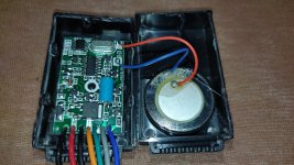
I don't think its useful, but i opened it up and checked if there is something that might be a vibrations sensor (but i don't even know what that looks like) :D
Anyway.. here is a pic. Maybe someone else sees something helpful ;)IMG_20210222_002438.jpg
 
Sparfuchs said:
First of all..here is the link: https://www.aliexpress.com/item/4000137951147.html?spm=a2g0s.9042311.0.0.27424c4dnmv0Q3
(i think the customer reviews contain lots of useful information ! Particularly the first one. Shown in the screenshot)
Based on what I can gather from the various info there, you'll have to directly connect the alarm *and controller* to the battery rather than going thru any of your keyswitches, because if they aren't both powered, it doesn't seem to work, if I am understanding correctly.

AFAICT, it works partly by detecting a signal from the motor being moved (spun). The problem is I can't tell if it is a phase wire signal (high voltage) or hall sensor signal (low voltage). Some of them seem like they mean the phase wire itself, and some aren't clear but don't seem to mean that. It's hard to tell because none of the ones with the info are actually in English, so I ahve to use google translate on them and that's often iffy at best for technical stuff. :/


If your controller supports "anti theft" mode engaged by a specific wire being grounded, then if this controller has an output that grounds itself when active, you could hook it up to trigger that, and it would make it harder to wheel the bike/scooter/etc away.
 
Sparfuchs said:
so the method with the "silent halls" doesn't use power if no motion is detected but the slightly noisily method does use a little bit power all the time its enabled, right ?
Basically, yes. There is really a tiny bit of power for any method, because the controller is still "on", but more power is used for the method that constantly makes a noise with the motor.


How do i know if my controller does offer one of those methods ? In the sabvoton software a saw a switch to disable or enable "anti theft" but i haven't tried it yet because i assumed it wont work without a anti theft line. But ill try and see what it does.
I don't know how yours works. If the manual (if there is one) doesn't say, you may have to experiment.


The method with the shortcuted phases seems a bit too dangerous for a beginner like me. I'm worried i might forget one day that they are shortcutted or something else goes wrong.
That's always a possibility...it's even possible (unlikely) for the switch to fail in a way that leaves some wires connected but others not.

And additionally its really hard to get a small key switch that handles enough current.
You won't find a small switch that does it; that's the problem. If you want to use a small *switch*, then the switch has to control a relay instead, and the relay will then be large. There's not really a way around the size problem. :/

Same problem with Delta-Wye switching, which some people have done to get "two speeds" with their actual motor.
 
Sparfuchs said:
I don't think its useful, but i opened it up and checked if there is something that might be a vibrations sensor (but i don't even know what that looks like) :D
Anyway.. here is a pic. Maybe someone else sees something helpful ;)IMG_20210222_002438.jpg

That large blue cylinder may be a motion sensor of sorts. There are devices that look like that which have a ball inside, and a "cage" along the length, so if it's tilted the right way it touches the ball to both conductors and it engages the switch.

If you disconnect the alarm from everything else, and clip your multimeter leads to each end of that blue cyclinder, set the meter to continuity or 2ohms, then move the alarm slowly around at different angles, then if it is one of those switches, in some positions it will give you continuity or a very low ohm reading, and every other position will give you OL or open circuit.
 
amberwolf said:
Sparfuchs said:
I don't think its useful, but i opened it up and checked if there is something that might be a vibrations sensor (but i don't even know what that looks like) :D
Anyway.. here is a pic. Maybe someone else sees something helpful ;)IMG_20210222_002438.jpg

That large blue cylinder may be a motion sensor of sorts. There are devices that look like that which have a ball inside, and a "cage" along the length, so if it's tilted the right way it touches the ball to both conductors and it engages the switch.

If you disconnect the alarm from everything else, and clip your multimeter leads to each end of that blue cyclinder, set the meter to continuity or 2ohms, then move the alarm slowly around at different angles, then if it is one of those switches, in some positions it will give you continuity or a very low ohm reading, and every other position will give you OL or open circuit.

You were totally right about the blue cylinder and helped me a lot to solve the problem.

What i did was connecting the red and black wire to the battery and if i press the lock symbol on the remote the alarm is engaged. As soon as anybody moves the bike a extremely loud alarm rings out the thing. If i press the unlock symbol the alarm is disabled. Pressing the ignition symbol puts battery voltage on the orange wire. So this can be used as a remote ignition switch.
I haven't checked out the other wires because now it does all i wanted it to do. I guess the other functions are detecting movement on the the motor its self and triggering the alarm (what i don't need because the vibration sensor is totally sensible and does quite the same) and locking the motor when movement is recognized (what i can't do without anti theft line and function i guess and also don't need because i'll use a bikelock anyway to lock the bike on objects so no one can take it away or dismount my rear motor wheel).

So for me its solved and im very happy with the solution. Thanks a lot
 
Back
Top