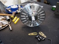
APL's DIY axial-flux motor

The Motor Gods were smiling down on me today. I got the phase wire holes drilled without a hitch, plus, the bearings
came in, and I was able to finish turning the surfaces. :)

Bearings are NSK #2006, and a SKG #2008.
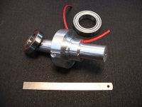

Bearings.jpg


I was able to push a 5mm O.D. wire through without to much trouble, and could probably get a 6mm with a little
bigger hole. Phase wires aren't going to be near that big, but it will be nice to add some shrink tubing.
I have to chamfer some edges yet.
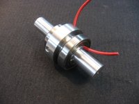

Bearings & Phase Wire.jpg


The 68mm #2008 bearing is huge! I'm definitely not saving any weight anywhere yet.

I think I might be building a tractor motor... :?
 
Decided to come back down to earth on the controller, no since getting carried away yet. I'll try it stock, and see
what happens,..then go from there . If I can't get my jollies from it, then I still have the option to modify.

The whole thing is illegal anyway, unless I put the 'offroad' tag on it. Still,.. it comes down to being responsible. We all
have cars and motorcycles with way more power than we use, the whole Classic car/Hot Rod industry is geared towards this.
It all comes down to how you use it. Theres nothing wrong with letting it out on a backroad somewhere, as long as your
civil in town.

I have a feeling that the new set up is going to be just fine, it's just so easy to get obsessed with the idea of power. :wink:
 
Sometimes more power is necessary for a few seconds here and there, but not under any other conditions.

For example:

My trike (and previous bike) are like that--just need the 3-4kW+ for 3-5 seconds during acceleration from a stop to get to the 20MPH max allowed, so I am not pissing off the impatient drivers behind me at a light, since it's very common for me to end up the first one in line at a traffic light (and in some (many?) drivers' minds, conciously or not, generally whoever is in front is "at fault" for the rest of them having to wait, and if that person doesn't take off like a bat out of hell to get out of their way, the rest may start honking or even just go around them (whether there is space or lanes to do so or not).


Sometimes I need the power for longer, like when hauling really big/heavy loads, like the annual dog-food-clearance-haul, or the occasional odd thing like the piano, but mostly it's just the momentary acceleration. Past that point, it's 1000w or less, unless there's a lot of wind. (trike isn't exactly aero).
 
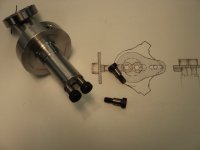
I found some 3/8" x 5/16" shoulder bolts for the axle ends, locally,.. I didn't feel like sending off for metric units
at this point. These will work to test the dual bolt idea. And since this is going into my bike for testing, it all
has to conform to my dropout/motor mounts.

The shoulder goes into the axle about 1/8", and the rest is 5/16" threaded, so it doesn't take up to much axle meat.
It worked out to be a nice snug fit, and actually gives me a little confidence that it might actually work. :)
Next step will be to make the torque arms that the bolts go through.


Axle sholder bolts.jpg


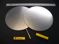
Also got the stator plates today! And a brand new 10mm end mill to chew them up with. The next step is to figure
out how to get them mounted on the lathe, so I can turn the center holes, and size the outer diameters.


Stator Plates.jpg


They are .250" / 1/4" thick aluminum, and are looking a little whimp now that I'm looking at them. Almost wish I
had gone with 3/8" instead.
Oh well, theres plenty of chances to ruin them yet, and I can always make another pair, if it doesn't work out.
 
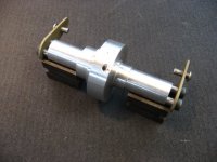
I took some soft 1/8" strap and made up some torque arms, I don't expect any wallowing, but if it does, I can
use some better steel. They came out very tight. Luckily I found the hole centers, which get used once in a
blue moon, and even had some 3/8" ones. Otherwise it would be difficult to get a good fit.


View attachment 1


That wraps up the axle for now, all thats left is the stator mount bolts.


Torque arms.jpg


Next, I have to mark off the 24 electro magnet slots, although I might be going to 21, since the space between
the slots is fairly narrow.
From a strength point of view,.. I'm basically drawing a doted line for breakage if they're too close together.

Started looking at N50 magnets today. 30mmx10mmx4mm. Looks like they're going to come from China. So I
suppose I better order some soon, because it might take a while.

Any advice on magnet quality?
 
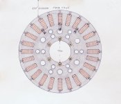
Stator Plate drawing. Not perfect, but the basics are there. Probably wont go with Halls until later.


Stator Plate.jpg
 
I'm so tired right now that I'm probably either just being stupid or misunderstanding the drawing, but isn't that actually the *rotor* plate? It looks kinda like it has stacks of magnets with a spot for a set screw at the top (outer circumference)...but I can't be sure.

The stator has all the windings and wiring on it (because if it was the rotor the wires would instantly get all twisted up and torn, unless you use brushes to connect to them from the outside).
 
Confusion is understandable. I know that it's clear in my mind, but others don't see my thoughts, so it's a little difficult
to understand what it is their looking at. A 2D drawing doesn't help.

I'm sure there's a lot of head scratching going on, and some people are waiting to see just what it is that I'm actually
doing! Sorry about that, but it should be clear, once I start to get things assembled, and have pictures.

At that point you might say, "that'll never work!" :) And you may be right! The whole thing is a big gamble for me.

I should have built it first, and shown it after,..my mistake,.. but thats what makes it exciting!

Anyway,.. That is the stator plate, to be bolted to the axle, outside view. On the other side is the coils, and then another
stator plate. The slots and set screws are holding the lamination stacks. The electromagnets all act like bridges between
the two plates, and solidify the whole thing, although I'll probably have to use some Locktite to help with that.

The stator looks just like the rotors, which also have 24 slots milled into each of them. So their easily confused.

The PM magnets will be bonded to two metal rings that are screwed to the outside of the rotors, and will all fit into
the slots, facing the stator. The back of the rings will be visible, and removable, from the outside.
The motor will have easy disassembly this way as well.

The reason I wanted to design it that way was, for the first time, a person can easily change out PM magnets and rings,
and also easily adjust the air gap between the electro, and PM magnets. (shim stock)

Don't know if it's going to work out this way, I might be trying to do too much at once.

The original idea was to have a motor that can be configured in different ways, with different windings and magnets,
up to a point. But now I'll be happy just to see it run, and save me from the embarrassing 'flop'. :confused:
 
I don't have much to show, for all that it's taken to get to this point. A lot of measuring and head scratching, trying to
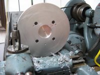
figure out how to go about turning these plates. I decided to screw them both together, since they will be virtually identical.

Then they needed to be bolted to the face plate, so I could take a few thousands off the faces, and get everything flat.
It's a good dry run for the rotors, which are next, and will need to be a little more perfect, since they will be spinning,
and have to fit the bearings tightly.


Turning the Stator.jpg


Trying to bore the first center hole was a real challenge as well, and seemed to defy all logic. I finally wound up just
working on a 10mm slot until it was bored all the way through, and the center pice just fell out.

The next center hole will be slightly smaller, and then it's on to turning the outer diameter down about 1/4"
 
I finished up all the turning, and everything came out pretty good, although they are a bit thinner than they were.
I just hope I can find some set screws small enough to go in the outer edge, and clamp the laminations solid enough.
I don't like the way they weaken the diameter, and it's a set up for cracking, but I don't have a better idea at this point.

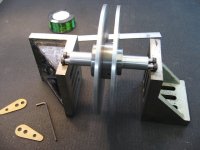
At least I was able to slide them onto the axle for the first time, and get it looking a little more like a motor for once.


Mounted stators.jpg


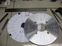
The next step was to mark off the electromagnet slots that are getting milled in the plates. I decided to go with 21
instead of 24, for a bit more space between them. Better air cooling, and more room to add larger wire.
It will run a little rougher, but I feel better about it, strength wise. It will probably feel like a Harley. 8)
On the 8-1/2" diameter, it came out to 32mm per slot.


Stator layout.jpg


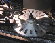
Now it's on to the mill. I made up a center plug/hold down that allows it to turn, but keeps it on center.
Next will be a pointer that locates the center line, and then it's just a mater of rotate, and lock.


If I had a rotary index table for the mill, it would make this job a lot easier, I could just go by numbers, and it would
come out perfect. But I don't, so I have to do it the manual way,.. good enough for the bikes I'm riding... :)

The slots will be round on the ends, so I'll have to square them out somehow.
 
APL said:
I finished up all the turning, and everything came out pretty good, although they are a bit thinner than they were.
I just hope I can find some set screws small enough to go in the outer edge, and clamp the laminations solid enough.
I don't like the way they weaken the diameter, and it's a set up for cracking, but I don't have a better idea at this point.

Making the perimeter of the outer edge thicker would have helped by providing more material for the set screws. Of course, that thicker piece of aluminum would have been more expensive and would have required more turning and material removal ... and it doesn't help much now ...
 
I think so too wtuber, that would be the answer, a thicker outer ridge. Although, it would have to be on the inside, because
the rotors will be very close on the outside face, which is the air gap.
But the coils will be on the inside, so they would be crowded as well.

Hmm.. I thought about putting the set screws underneath the laminations,.. but it makes them hard to get at, and the
thickness issue is the same. I would have to mill more slots in order to get at them.

Perhaps the answer is to use 3/8" plates, and leave the whole coil section of the plate thicker. Removing material from
the rest of the plate, for lightness. The cores will have to be a little longer, but thats probably not an issue.

Well, whats done is done,.. cross my fingers and hold my breath. Maybe this will work. :)
 
How about notching one or both sides of the laminations to positively locate them in the slot. (They'd have to be tilted to drop them into place. You then install a "wedge" assembly above or below each stack. The wedge could be made of two wedge shapes (think of a rectangle sliced diagonally) that are held together by a screw that drives each wedge toward the other causing the height of the wedge to increase as the screw is tightened and the wedges slide against each other. The bottom wedge might be notched to keep it positively located in the slot. There are other ways to make a compressing "block" as well.
 
I see what you are saying,.. yes that would work. I've seen the wedge system on other things, and it can create a lot
of force. It got me thinking about a possible cam system as well, that could be installed on the bottom, for tightening.

One problem with installing the laminations the way you described, is that the windings would have to be done with the
cores and plates in place, instead of individually, outside.

Having the laminations locked in place from side to side like that would sure be nice though, all the magnetic forces
are going to be trying to shake them loose.

A good wedge or cam, or some type expander that is easily accessed from the bottom, where theres a lot of meat to work
with, is a good idea, your right about that. :thumb:

I was hoping to install all the windings and cores, and do all the phase wiring connections, with one plate installed on the
axle, and then slide the other plate on, over the remaining core ends, on the other side.
 
Here's another bottom clamp idea that would probably be easier to make.

Its a horrible sketch and not to scale, but hopefully gets the point across. You notch the bottom of for your lamination slot. That creates a key so that you can slide in a threaded rod that has been filed/milled to fit the slot. The threaded rod has a long threaded nut installed on it that can then be spun to press upward on the bottom of the lamination stack. Something like this could be made with minimal fabrication to off the shelf hardware. Maybe the notch for the bolt is a V shape to make fabrication simpler.

The long nut could also be a regular nut with either a washer stack or other spacer extending up to the lamination stack. That might be better since it would tend to isolate the stack from torsional friction from the nut.

 
I got the locator/pointer bolted down, and milled all the slots, without any trouble. But after seeing the 30mm slots
on there, I thought that they looked pretty whimpy compared to the beef of the rest of the motor. :(
The reason had 30mm before, was because the 24 slots wouldn't allow anything bigger.

30mm slots..jpg


But 21 slots give it more room.

So I took another look at magnet availability, and decided to go with N52 40x10x4mm units. Another 10mm gives it 42cm
more area overall, but still is not that far off from the H35xx motor I'm using as a base to work from.
The H35 PM magnets are 'about' 4mm thick, and 35x10mm.

I also found some USA SAE N52 magnets that were 1-1/2" x 1/2" x 1/4" which are slightly bigger, and have a whopping
27.6 pounds of pull each! Close to twice the pull of the ones I'm getting. But also several times the cost at 50 for $175.
compared to the $35. for the ones I ordered.
One good thing about this motor is that the magnets can be changed.

Nice to know that a monster version could be next, if this motor works out. But for now, I have to stay within the H35
parameters, and not go to far astray. Plus, I don't want to spend to much money, until I see it spin!

I'm pretty sure that the relationship between the core size, magnet power, back iron, and current input, all need to be
balanced, otherwise if one of the those is excessive, it will most likely be wasted.
 
You must have slipped that in while I was composing!

Yea, I like that,.. easy enough to do, maybe a small 'point' could be put into the top of the nut to lock the stack in place.

I was also thinking of the possibility of maybe putting a long screw, or pin, down from the top, along the 'side' of the stack.
Slightly notch the stack side, so that the screw would lock all the laminations in place.
 
APL said:
You must have slipped that in while I was composing!

Yea, I like that,.. easy enough to do, maybe a small 'point' could be put into the top of the nut to lock the stack in place.

I was also thinking of the possibility of maybe putting a long screw, or pin, down from the top, along the 'side' of the stack.
Slightly notch the stack side, so that the screw would lock all the laminations in place.

I was noodling some ideas that would have structure wider than the rotor plate, but was unsure how that might affect your windings. I'm probably not 100% clear on how all this goes together.
 
Well it's a conundrum thats been bothering me for a while. One problem is that the ends of the cores are sensitive
to many things that are going on there, since thats where all the 'business' is happening. So it's not just a mechanical
problem.

If I reduce or add any material on the core ends, then I change, or affect, the flux density and performance, as well.

Ideally, the shape of the core should look like an 'I' beam, being a little thinner in the middle, and thicker on the ends.
This is the way most motor laminations are set up, and saves weight where the windings are, and expands the area on
the ends, where the PM magnets are passing buy, for a bigger foot print.

Unfortunately, the I beam shape doesn't help to lock anything in place between the stator plates on this design.
One idea would be to reverse the I beam shape, and have the middle of the core a few millimeters wider than the ends.
then the two stator plates would keep them all locked and centered.

But, more weight. The weight of the cores is one of the biggest contributors to the net motor weight, and is probably
over 5lbs, so it's a good idea to try and figure out the minimum amount, and yet keep from running into core flux
saturation under the max amperage to be used.

I could further machine the center of the core, for the windings,.. but then it makes for a complex core shape, something
I was hoping to avoid. I was really hoping to get just a straight bar to work, for simplicity, but it may not happen.

Anyways, sorry for rambling on,.. too much coffee. Yea, it's hard to noodle when the design is unclear, hopefully I'll get
it looking like something pretty soon.

Keep on working on it though, your input is really helpful, and appreciated! You have lots of good ideas, and I'm looking
forward to seeing more.

It's a prototype, so not to much matters at this point, the first one of anything, is laden with problems. It usually takes
about three try's to get things looking right.

I looked around for set screws a bit, and found some 3mm stainless ones that looked like they'd fit the bill. They are used
in guitar bridges, so I can get them in twelve packs pretty cheap. I'm not to hot on tapping 42 of them with a tinny winny
little tap though!
 
If you like, I can split off all the posts in this thread about your motor development, and move them to the motor section. I think that might get you more answers.
 
Well,.. I am in the wrong category, ..I hope that it's not to much work for you, that would be great!

Into the lions mouth,...engage.. :thumb:

Thanks Ron! :)
 
Feel free to edit as you wish. Let me know where it will be , and if the thread has a new name?

Looking forward to getting help on this, as I'm heading into deeper water,..with pole counts, and phase wiring.

Thanks again, thats awesome!
 
Here are the stator plates with the 40mm slots, 21 cogs per side. I had plenty of opportunity to practice my swear
words on the corners. Used a 1/8" end mill, and the learning curve was brutal.


40mm Stator slots.jpg


This would be a perfect candidate for the Big Blue Saw, or CNC, and would have been perfect,.. but thats not DIY.
Or at least low buck. I'm trying to keep this motor in the realm of the home shop as much as possible , plus, I'm a
really cheap SOB!

I put some air flow holes close to the axle, but I'm not sure if the air should be made to flow from the sides in, or
from the top down yet. I would think centrifugal force would help to throw it outward, and should be made to
work that way.

I'm going to need some help with pole count, and spacing. Far as I know, windings are made in three's, and PM pole
magnets are made in divisions of two's. So, 21 windings,.. 22 poles? Surly it's more complicated than that. This info
is a bit invisible, or maybe I'm just not using the right search words.
 
APL said:
This would be a perfect candidate for the Big Blue Saw, or CNC, and would have been perfect,.. but thats not DIY.
Or at least low buck. I'm trying to keep this motor in the realm of the home shop as much as possible , plus, I'm a
really cheap SOB!

The pedicab manufacturer where I work gets a lot of plate parts laser cut or waterjetted locally. While the minimum charge is $150, the per piece cost is so low that it makes no sense to do it in-house except on a prototype basis.

It's something to consider if you decide to make copies of your motor.
 
I'll have to look into it locally. I'm pretty sure this motor is going to shake and shimmy, and probably be noisy as
hell, with all the imperfections that I've put into it. Still,.. I've seen worse on Youtube, and they seem to do well.

Water jet would be nice, so precise, and all the holes would be done. To bad there isn't a 3D material that would
hold up, that would be the ticket.

At the moment things are evolving to fast, so it's to early in the game, and I enjoy prototyping, except for the 42, 3mm
tapped holes that I'm doing now,.. who designed this thing anyway? :confused:

I had a 'think out of the box' moment the other night. I was thinking that a substitute for laminations might be to use
1mm rods stacked up in the slots. The advantage being that they will take on any shape, and are easy to cut to length.
I know that they make silicon steel wire, but of course it's not available in small quantities.
Anyway,.. just a thought, something to toy with in the future...
 
Back
Top