Total headless mode for BaseRunner? (No display, POS sensor or torque sensor)

tribbloid

1 µW
Joined
Aug 28, 2022
Messages
2
Main article:

https://bicycles.stackexchange.com/questions/85589/can-the-grin-technology-phaserunner-series-be-used-in-total-headless-mode-no-d


One of my old e-bike has a broken component and is subjected to upgrade, as most of the vendors have either disappeared or declare the component as end-of-lifecycle.

I'm considering Grin PhaseRunner ESC:

https://ebikes.ca/product-info/grin-products/phaserunner.html

and its successor, Grin BaseRunner V4/V5:

https://ebikes.ca/product-info/grin-products/baserunner.html

as the next ESC, it has good customisability & compatibility with many components. But there is one problem: According to its manual, it can only run with a PAS or torque sensor, or both.

Unfortunately the only standard Bottom bracket standard I could use are SRAM GXP or SRAM DUB, none of which has a compatible sensor interface.

So my only option is to use no sensor at all, and rely on throttle control. I may be able to upgrade to an optical flow based sensor later, which is agnostic to BB standard. Also, Both ESC can communicate with a cell phone with bluetooth, so a display appears to be redundant

So far, this feature has only been seen on Golden Motor xxx Pie series, and obviously, any motor integrated with a hub torque/PAS sensor. I haven't find this option in the manual, or any official build template. Is it possible?
 
thanks a lot. It looks like good enough for a GXP BB (DUB would still exceed its hole size though). Hopefully an optical flow sensor could appear soon and simplify the installation process

So no tensor/throttle only is indeed not an option :-<
 
I have a Baserunner Standalone edition + CycleAnalyst. I don't think it would be difficult to run without the CA and PAS. In terms of on/off, I've successfully shorted the on pin to the positive pin in the mains connector to power the controller on before. Similarly, I've used the CA in passthrough throttle mode before, which simply passes the throttle signal through the throttle pin on the CA DP connector. So I think you could successfully wire a throttle to the CA DP connector without issue.

For most companies the LCD and controller communicate using TX and RX pins. CycleAnalyst isn't like that, however. CycleAnalyst outputs a throttle signal, just modifies it based on various inputs like PAS. So it should be easy to fake. Check out the last page of the CycleAnalyst manual which has the pin out.
 
No need to fake anything.

Just hook up the throttle you wish to use, and set the BR/PR/FR up to use the voltage range it outputs, and respond the way you want it to.

Once programmed to work with your specific motor and throttle and battery voltage, etc., the *runner controllers don't need to be connected to anything except those devices to work.

Pinouts for the BR are on this page, for instance
https://ebikes.ca/product-info/grin-products/baserunner.html
to show you which pins to connect the throttle to.
 
I'm currently running a baserunner system on my standard moped style e-bike. I'm running it in headless mode and I have made the connections as per the diagram below. The issue is that I thought that e-brake is the motor cut off that you use with your brakes; so I hooked up the e-brake as per the diagram and when I turn on the system the throttle does not give any response although when I engage the brakes the motor runs at full speed. My throttle has 3-pin Julet style yellow pinouts; I am not sure where the signal cable and the +5V/Gnd goes; although I saw online and have tried couple combinations but nothing works. When I disconnect the e brakes; the throttle does not give any response to the motors.

What am I doing wrong?
 

Attachments

  • Screenshot_20230629_134845_Samsung Internet.jpg
    Screenshot_20230629_134845_Samsung Internet.jpg
    321.5 KB · Views: 18
Looks like you are wiring ebrake between battery voltage and the ebrake input, which is typically bad. If so, it may have fed battery voltage into the BR in places it shouldn't go, and might've damaged it.

Ebrake is usually a signal that is grounded to activate them; if you are using only a two wire NO switch then you would usually wire one side to the ebrake signal line, and the other to ground.

Some controllers have an analog input for ebrake, that controls variable / proportional regen. If yours is setup that way, then you'll need to input a compatible signal for the result you want. Or change the settings to match the ebrake hardware you have.

If your ebrake levers also control lights then you'll probably need to separate the two usages with a relay or other isolation device so the BR doesn't handle any of the current from them.

Throttle looks like it's wired correctly, assuming that the wires from the throttle are actually those specific signals on those wires.

If the throttle has been wired incorrectly at any point, it might have damaged it's hall sensor. YOu can test that by using a 5v source (USB charger, etc) to power it, and move the control while monitoring the signal wire with a voltmeter on 20VDC. It should vary from around 1v or less to around 3v or more.
 
Last edited:
Thanks for the input; I might have to try with a multimeter afterall. About the controller being fried; I don't believe that happened because the motor still spins upon engaging brakes(while ebrake pin is connected as per the diagram) and I could run all the tests with the phaserunner suite.

However, the throttle didn't respond when connected individually initially or even with the ebrakes.
 
It doesn't have to be fried to be damaged. It can still function except for whatever part(s) were damaged, and then those can still function but incorrectly.

For the throttle, if it's initial wiring was incorrect it is possible to damage it, so it would never work correctly or at all in that event, and so the problem might only be with the throttle and not the controller.

Or it could be neither has a problem and only the wiring is incorrect.
 
So I finally have results after measuring with a multimeter.

When I connect only the throttle; my voltmeter reads ~0.85V between the Signal and Ground. It reads ~4.7V between ground and +ve. When I move the throttle; the signal and ground starts going up from 0.8V to ~4.5-4.7V; which I believe is how it should behave.
Even after this, there is no movement on the motor.

BUT

When I measure the Voltage between the blue cable (ebrake) and the red or orange cable(on/off, they are shorted); it reads ~56-57V, which is the charge of my battery. When I connect those two; the motor speeds up to what looks like max speed. Moving throttle during this period however doesn't have make any difference.

I cleared my doubts that if it was wired incorrectly(it's not) and neither is the throttle or controller dead. Mystery for me is why does the motor only respond when the Blue and Red/Orange cables are connected. Could it be something that I need to change in the phaserunner software?
 
So I finally have results after measuring with a multimeter.

When I connect only the throttle; my voltmeter reads ~0.85V between the Signal and Ground. It reads ~4.7V between ground and +ve. When I move the throttle; the signal and ground starts going up from 0.8V to ~4.5-4.7V; which I believe is how it should behave.
Sounds normal enough (many throttles only output up to around 4v or less, but some go higher, which is fine).


When I measure the Voltage between the blue cable (ebrake) and the red or orange cable(on/off, they are shorted); it reads ~56-57V, which is the charge of my battery. When I connect those two; the motor speeds up to what looks like max speed. Moving throttle during this period however doesn't have make any difference.
Ebrake is normally a low-voltage signal, so you shouldn't need to measure from it to battery voltage. It will normally be grounded (0v) when active, and 5v when inactive.

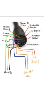
As I noted before, your diagram shows you are wiring it to run to battery voltage, which is normally very bad for the controller, and can damage the controller's ebrake signal input (or other damage to the MCU that may vary depending on the controller's specific design, causing permanent incorrect behavior of the system). It might not totally kill the controler, but it is unlikely to operate correctly wired this way.

Normally ebrake signals are run to a brake lever that has it's other wire going to ground, not to a voltage.

Depending on the version, the Baserunner/phaserunner also has the ebrake signal running to the throttle, so the throttle signal input to the MCU can also be damaged by the battery voltage, but even if it isn't. The throttle itself could also be damaged by this, depending on the sensor design used in it.

I don't know which BR you have, so you'll have to determine that and then use the appropriate manual:

The BR v4 manual (first dedicated BR manual version, before that the PR manuals are used; see below this section)
This states:
The CA3-WP device is plugged into the matching connector. All throttles, ebrakes, and PAS or Torque sensors are plugged in directly to the Cycle Analyst. The 6 pin PAS plug of the controller is not typically used. However, a short adapter is provided that should be plugged into the 9 pin Mains cable. This adapter serves two purposes • It links together the ebrake and throttle signals of the controller so that the throttle output of the Cycle Analyst can be used for both throttle and regenerative braking control.
whcih indicates the BRv4 doesn't directly connect the throttle and ebrake like the V2 PR, so if you aren't using that adapter on the mains cable then they are separate wiring...but the ebrake is still not a battery voltage signal, it is a 5v level signal. More info on it's usage is stated as
The Baserunner has an analog ebrake line on the 9 pin Mains plug that can be used to provide smooth variable regenerative braking force from zero up to the max regen phase amps. In order to use the regen features of the V3 Cycle Analyst, this ebrake signal must be shorted to the throttle signal so that a single voltage can control both regen and power. This is achieved via the short 9Pin to 2Pin adapter cable discussed in Section 3.1.
and
The Ebrake signal on the 9 pin Main cable is an analog input that provides proportional braking control if desired. This is pulled to 5V internally, while the throttle signal is pulled low. If the throttle and ebrake signal are shorted together, then the signal level will sit at 1.0V, allowing a single wire bidirectional torque control with 0-0.9V mapped to regenerative braking, and 1.1-4.0V mapped to forwards torque. If these signals are not shorted together then a simple ebrake switch to ground will activate maximum regen. Alternatively a secondary throttle can be wired to this input to achieve proportional braking without a Cycle Analyst, in which case the regenerative brake mapping should be reconfigured to have similar start and end voltages as the throttle signal.

From the PR v2 manual:
2.3 Throttle Cable The throttle cable is terminated in a 3-pin JST plug and is used for simple systems with just a throttle control of the ebike, with or without a V2 Cycle Analyst (CA) display. The ebrake line is also tied into this throttle signal, and with the default settings the throttle signal voltage can be brought below 0.8V to activate proportional regenerative braking, allowing for the potential use of bidirectional throttles for control of both forwards torque and braking torque.

The v6 manual has different wiring sections depending on whether you're using it headless or with a CA,
One section describing it
The Phaserunner V6 by default has both the throttle signal source and the regen brake signal source coming from the same line, Analog Input 2, which floats at 1V when disconnected. This allows for a single wire to control both power and braking. The signal can be shorted to ground via an ebrake lever to achieve maximum regen braking. If completely independent throttle and regen brake signals are desired, then the throttle signal source can be changed to Analog Input 1. Separate wires can be used to control braking versus throttling..


The orange and red wires should get connected together when you wish to turn the controller on, but you should not connect any of the control signals to either one of them.

The orange wire takes battery voltage to supply to the controller LVPS that creates lower voltages to run the controller MCU and devices like throttle, etc.


And if you haven't already run the setup software and configured the BR for exactly how your system is setup and which motor parameters / limits / etc the system uses, you will need to do that for it to operate correctly (or at all), as it is not a plug-and-play controller and requires this setup to be completed.
 
There you go!! That did it. I shorted the Blue ebrake to the throttle Green signal and I have a functional throttle. Motor spins up slowly and gradually but achieves the max speed at only 1.3V of throttle signal(by twisting the throttle ever so slightly); so I need to adjust parameters in the Baserunner Suite. I have a Baserunner Z9 V5 controller. Thanks; I'll update if my desired output is achieved.
 
I did my victory dance a little too early. I'm not able to get a proper output from the throttle. It still maxes out around 1.2 to 1.3 V; which is barely a 2-5° twist and the motor reaches the maximum speed. Just a slight touch and the motor starts softly, until I twist a bit more and it shoots me at max speed. With a normal controller, this degree of twist would barely result in a 6mph speed.

Not sure what I can fix here.
 
Have you configured the BR in the setup software for your specific parts, system, usage, and desired operation? If not, you should do that first.

Remember the *runners are current (torque) controllers, not speed controllers like the typical ebike stuff is, so the throttle controls the amount of current fed to the motor, not the speed of the motor. It will respond differently when riding vs offground testing for this reason, so some setup steps have to have their effects verified in test rides.

And for this reason, if your new controller has a much higher current limit than your old one, and the battery supports that much current, a much smaller throttle input will cause a much higher current to the motor and so more power delivery from the system.

There should be settings in there for throttle response. The manual should have this info, if not and if not in the program's help or other online info, you might check out the Phaserunner/etc setup videos by Grin that probably explain it. It's possible but unlikely that they took away control of throttle response so that it would only be handled by the CA (which can do a good job of this, but where possible it's good to directly handle this in the controller for FOC types, like the *runners).

Regarding the actual throttle output voltage, if you get only that 1.2-1.3v voltage out of the throttle even with it not connected to your system and just powered by a separate 5v supply, then it is likely damaged or built wrong, as that is usually the lowest end of it's output range.

If it has a normal ~1-4v-ish output range in that test, but only has 1.2-1.3v output range when connected to and powered from the BR, verify that it gets 5v from the BR.

If it doesn't get 5v, but something significantly lower, then something is dragging down the BR's 5v supply which can cuase all sorts of misbehaviors. Disconnect things from the 5v line until only throttle is left, and if 5v doesnt' return, disconnect the throttle too. If the BR 5v still doesnt' go back to normal then something is wrong with the BR or it is not getting enough voltage to the battery to operate.

If it does get 5v from the BR, then something else is dragging it's output down, such as the brake line input tied to it, so you can disconnect that to test if it goes back to normal voltage range. If it does, then something on that brake line is dragging it down, and if there is no external low resistance between that line and ground, the input on the BR it is wired to might have been damaged by connecting to to battery voltage and be causing the problem.
 
Back
Top