adam333
1 kW
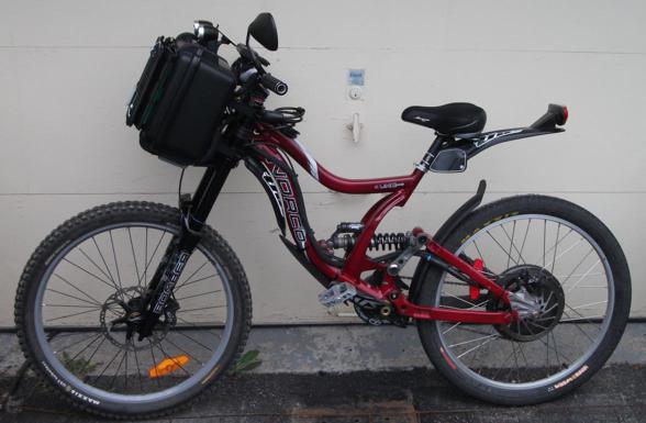
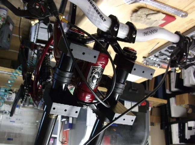
I made some modification to upgrade the bike utilities. Initially:
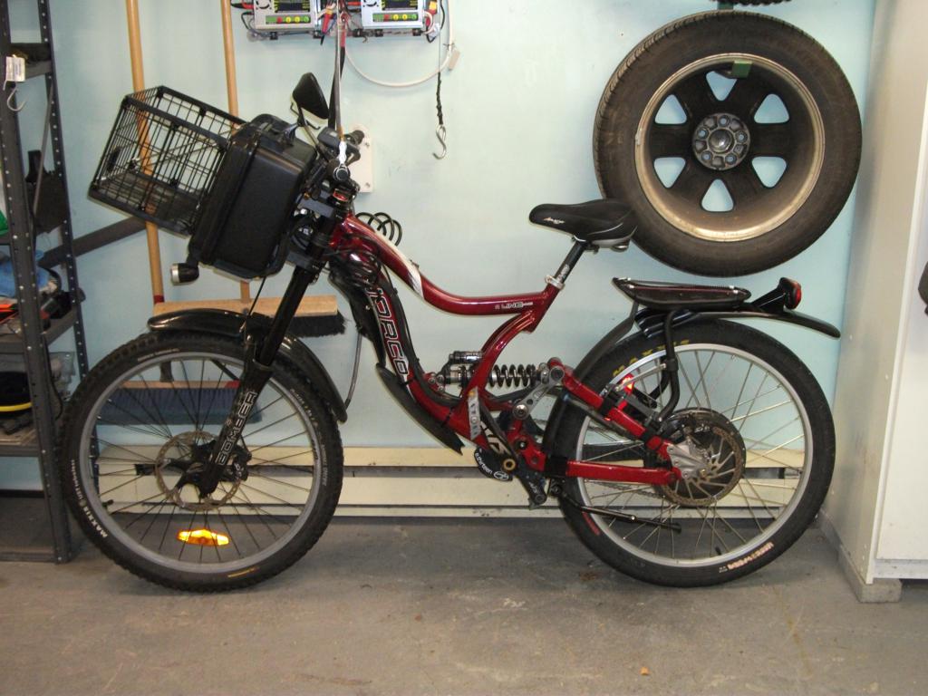
Now I basicaly added a DH kickstand designed to fit an A-Line + the rear mudguard is now acting as a mudguard.
Steering at low speed is a bit odd although I get used to it quickly. As soon as you go above 25kph, the feeling is awesome. Steering is really quick, I would compare it as driving a 400 lbs motorcycle. Pretty stable at high speed and in curves. The weight at the front prevent any chance for me to make wheeling even if I didn't increase my wheel base distance. ( controller is limited at 45 A though )
Data:
Battery pack weight : 23.4 lbs ([100.8V], 24S, 2P, 30C, 16Ah Lipo) [specific energy 130-200 Wh/kg]: http://www.hobbyking.com/hobbyking/...lightmax_8000mAh_6S1P_30C_AUS_Warehouse_.html
Bike weight with battery pack : 96.4 lbs
Bike + driver ( me @ 175 lbs ): 271.4 lbs
Max speed according to CA : 88 kph ( 55 mph ) ( Controller is limited at 45 A )
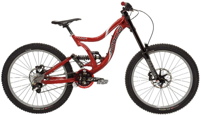
Bike: Norco A Line 2009 Park Edition, Medium frame: http://www.norco.com/archives/2009/?id=48a31c94f3e4f
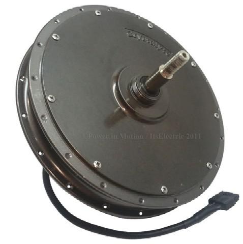
Motor : Crystalyte HS3540
Controller: Lyen 150V : http://endless-sphere.com/forums/viewtopic.php?f=31&t=18605
Schlumpf drive: 34 T front, 14 T rear. High Speed Drive ( 2.5:1 ) Efficient pedaling up to 50 km/h ( 31 mph )http://www.schlumpf.ch/hp/hsd/hsd_engl.htm
Run time : average is roughly 90min @ 35 kph (22 mph). Distance = 50km ( 31 miles )
Charge time : 3hours @ 1/2C ( limited by my power supply ). It will go down to 45min @ 2C once the new charger is built.
Charge cost : 0.20$ / 100km ( 60miles )
Average of 26 WH/km @ 35 kmh (22 mph)
Average of 35 WH/km @ 50 kmh (31 mph)
Now, the development part:
I only made one E-bike before this one, but the experience I got from riding in Montreal's road at 70 kph without suspenison is ... Frightening!!!
So, this time I openned the wallet and bought a DH Norco A-Line Park Edition 2009:
The Motor is a Crystalyte HS3540:
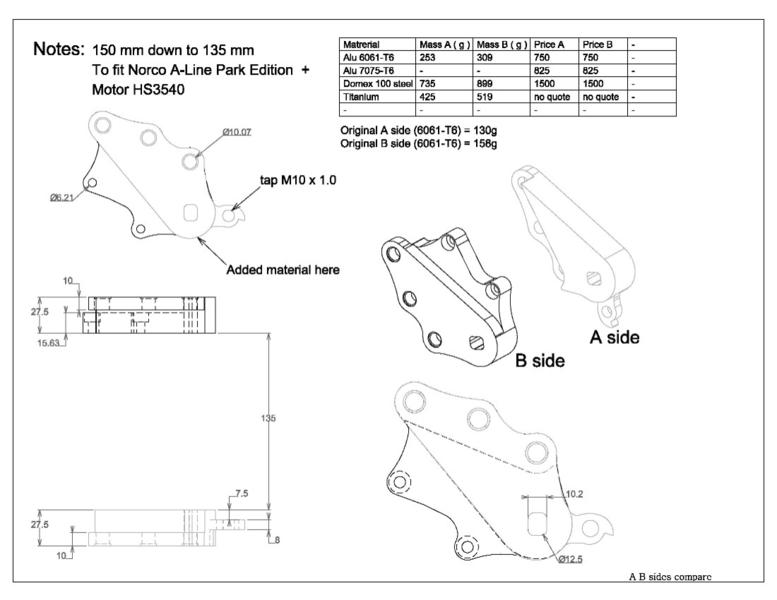
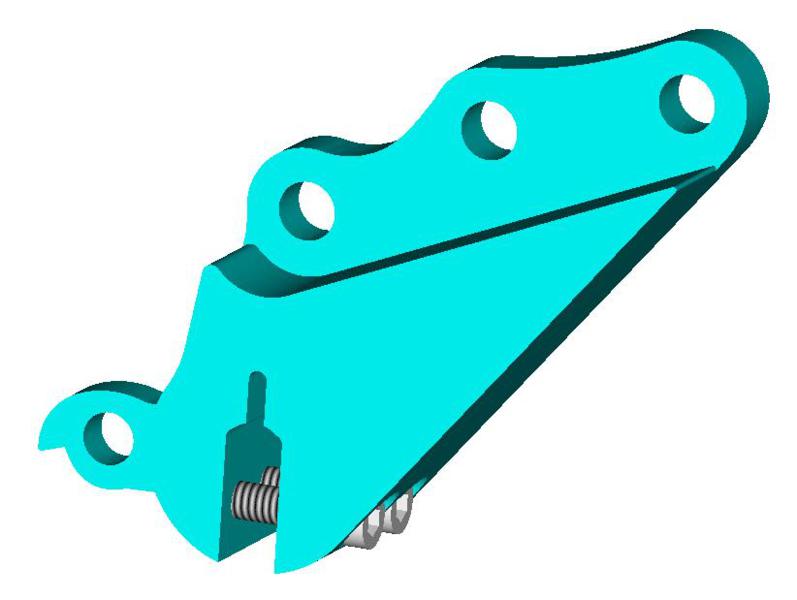
The 2009 A-Line was chosen mainly because of its removable dropouts. The first task was to scan those dropouts on a 3D scanner then rebuild those on the CAD.
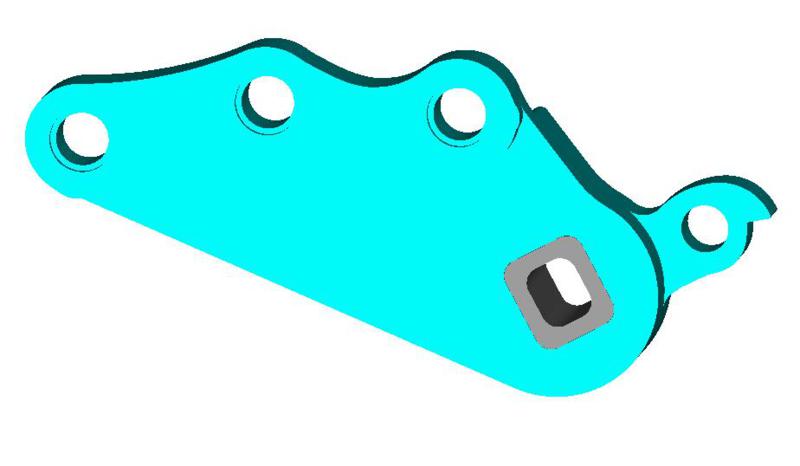
My initial goal was to make them stronger around the pivot, as well as the break attachment and add the 7.5mm per dropout to be able to fit the HS3540 in this 150mm frame.
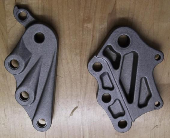
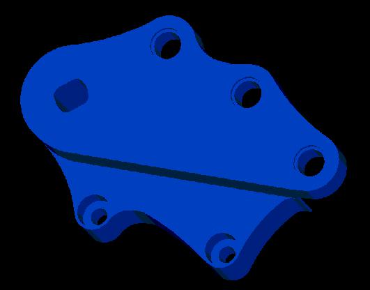
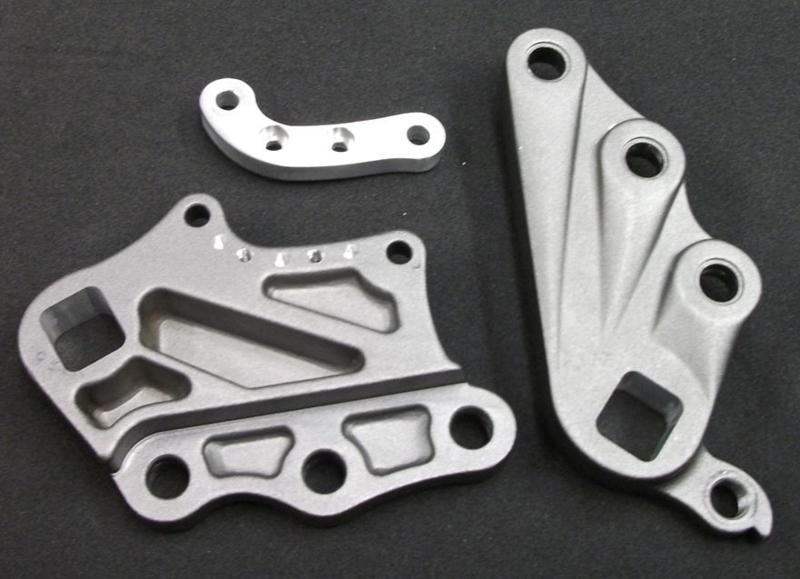
Original dropout:
changes to be made:
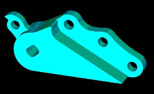
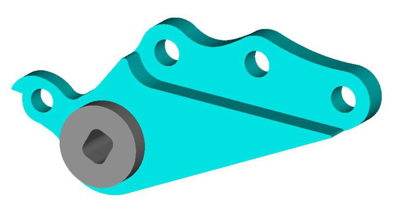
Rendered result:
I have a small CNC at home, but those dropout are too big for the machine capacity. The quote to make this set was 1500$ and 520$ from two local machine shop in 6061-T6 ...
Price was just too high so I went with the plan B. (modify and re-use the old drop-out then glue or press fit an insert as Doctorbass did.)
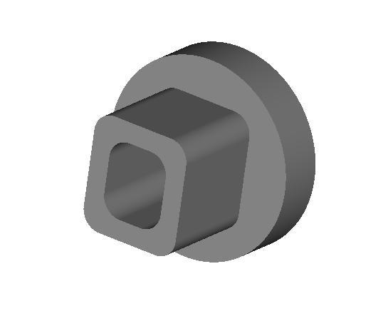
Insert in Dormex 100 or S.S.:
Result pres fit + DP 420 epoxy:
The extra 7.5 mm is included in the insert to fit the 135mm requirement for the HS3540 motor.
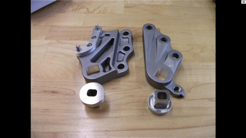
Now, from CAD to reality:
Each insert was 85$ and were made from Francois G. I did the modification on the Alu dropout with my CNC and a jig that I designed.
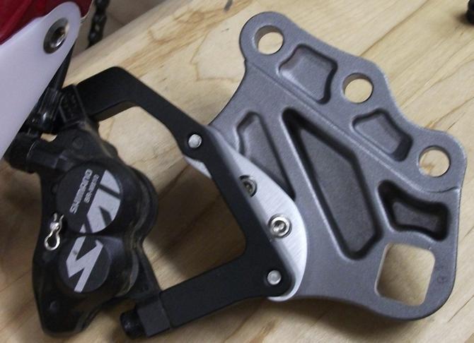
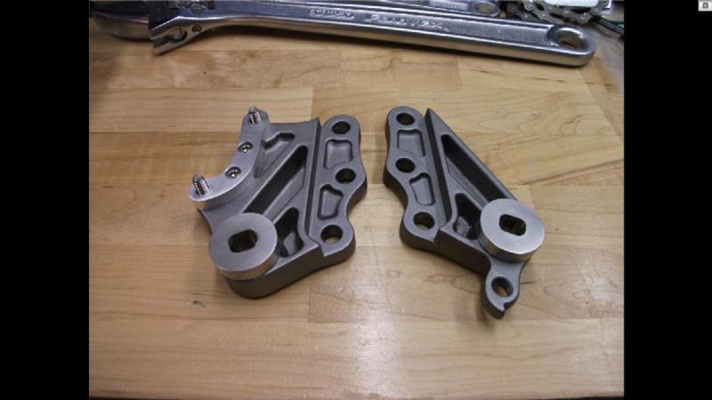
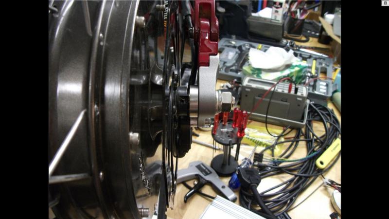
Press fit result:
Assembly part 1:
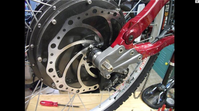
Assembly part 2 with nut, washer and lock washer:
Assembly part 3:
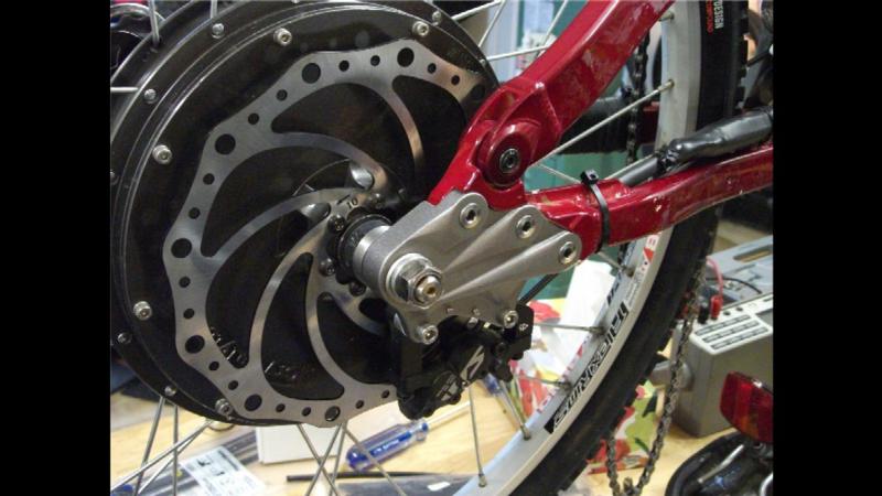
The wheelbase is then exactly the same (1170mm or 46in). 22 lbs of LiPo battery at the front, 100.8v, 16Ah and the Lyen controller limit the current at 45A. This weight/current set-up prevent the front wheel from lifting.
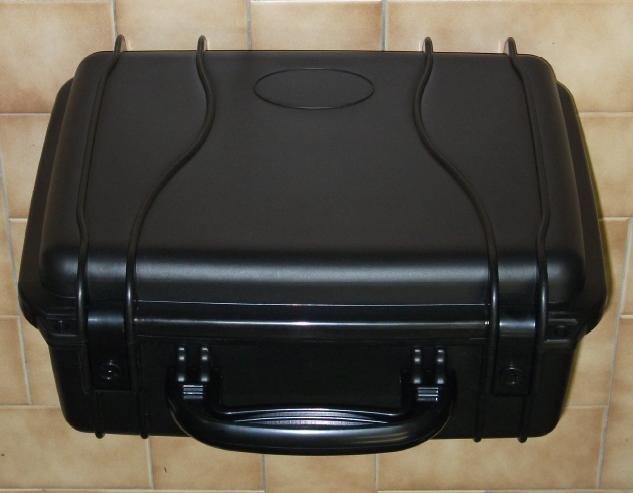
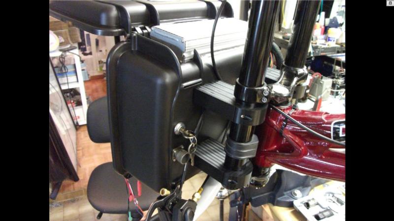
Front box: I use a Seahorse 520 http://www.seahorse.net/se520.aspx sealed lockable box for the Front battery pack:
They also offer to modify the box cutouts if you send them a 3d drawing.
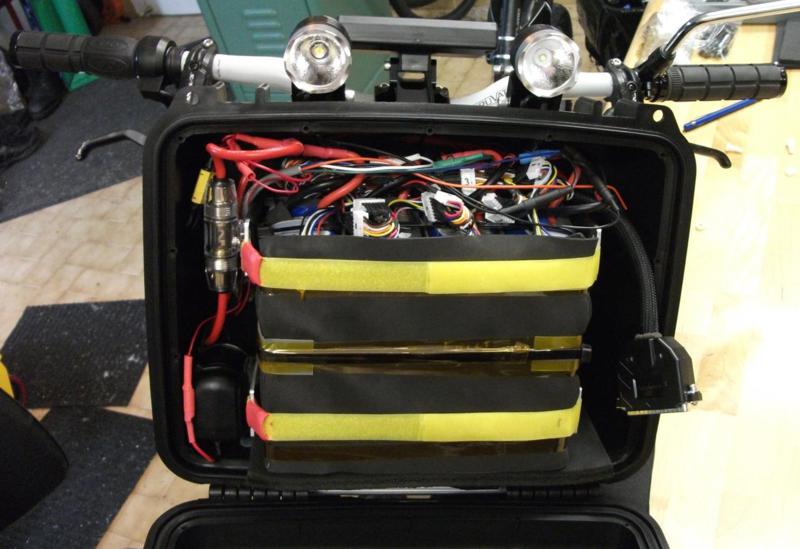
I made the box holder out of Black Delrin. The box contain 24S2P Zippy LiPo battery. 100,8V 16AH ( roughly 22 lbs ):
The battery is packaged in a 2mm foam layer and is removable by releasing 2 velcro straps ( not shown ).
Key switch + 6 pin connector for charging with protective cap + delrin holder are shown on this view.
The velcro strap anchor are bolted in the Delrin holder with a 1 1/2" bolt:
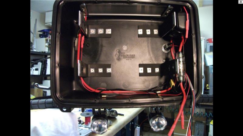
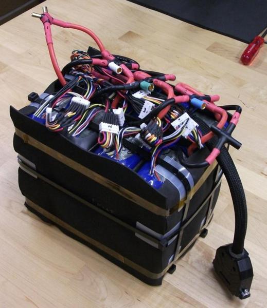
Completed battery pack ( 24S, 2P, 30C, 16Ah Lipo, 23.4 lbs)
I'm using 2mm foam around all battery.
The battery is removable as an assembly and come with the balance cable as shown below:
Battery strapped with velcro inside the box. Centered and constrained.
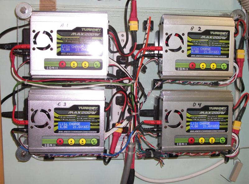
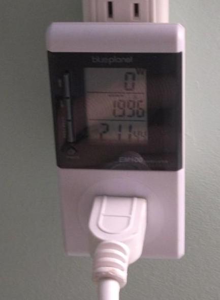
Charging area in the garage:
Home made charger with 4 x Turnigy 200W unit. They are connected in serie and each is powered by an isolated individual power supply. This allow me to charge without disconnecting anything.
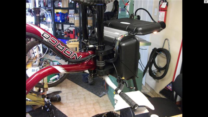
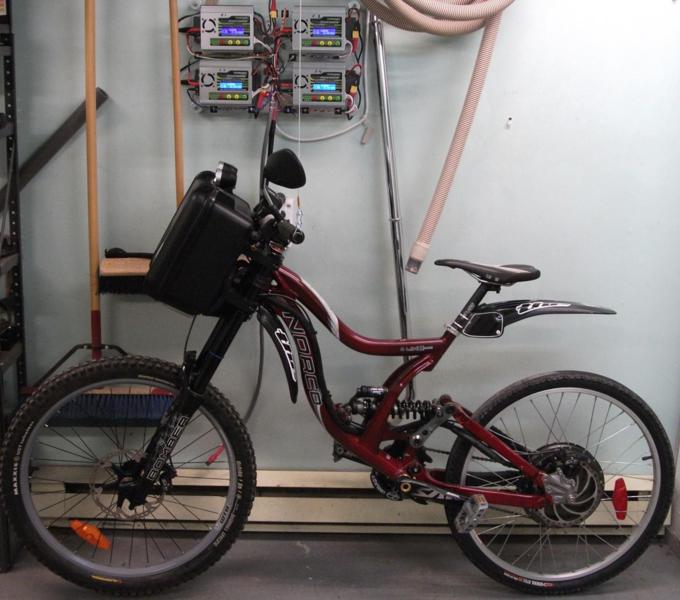
Not having a stand is annoying, so I made a hanging support to stabilize the bike. It allow me also to remove the front wheel easily as the wheel is 1/4" above ground.
After 935km done on my initial battery pack ( 41 cycles ) charging cost is just below 2$
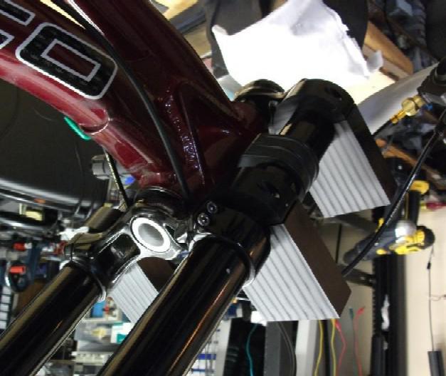
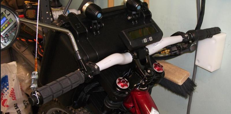
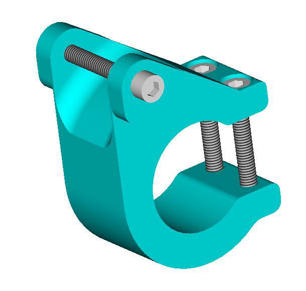
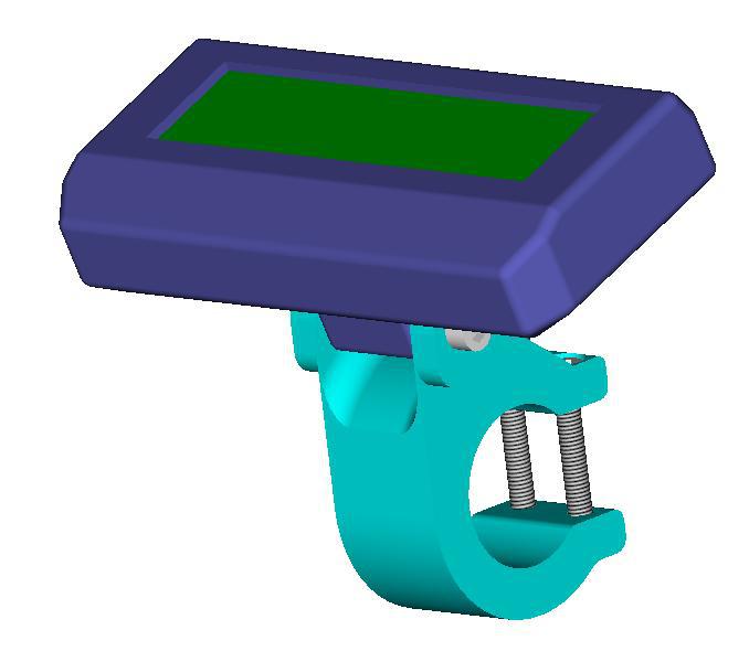
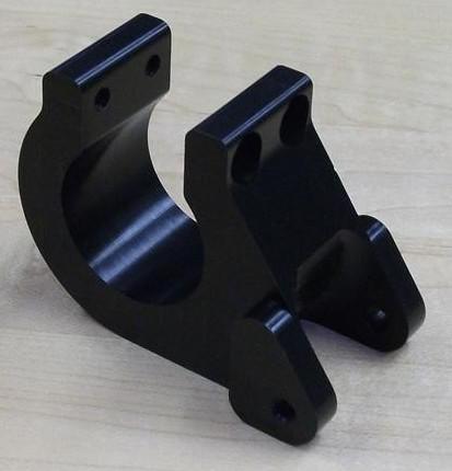
Of course the CA bracket didnt fit between the stems brackets... so I decided to make a stronger holder.
Material is black Delrin. Mass = 56g
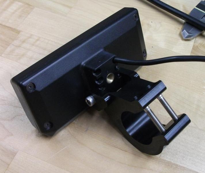
Since the Seahorse box is waterproof and there is limited air flow inside, I was worried about the battery temperature inside the box.
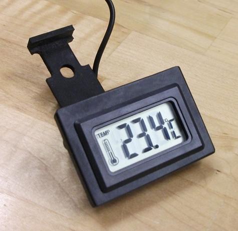
I designed and added a holder + temperature sensor to monitor it while running. ( temperature sensor is inside, near the top of the box )
After several rides under hot and sunny days, the internal temperature never reached 40 deg C.
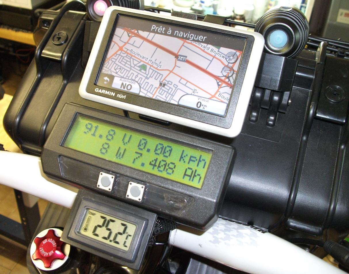
I also adapted the GPS holder on top of the box:
Bolted from inside the box, (sorry about the muddy picture )
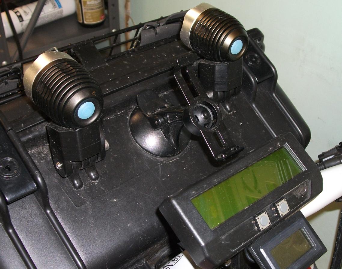
Temp sensor + GPS in place:
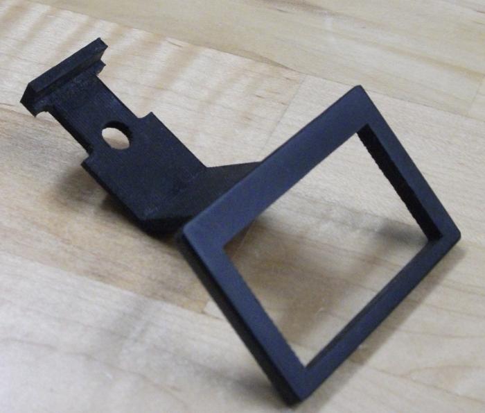
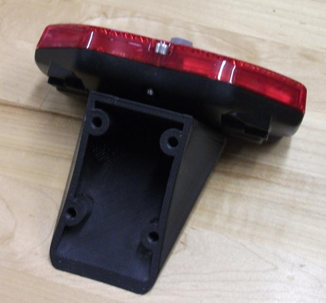
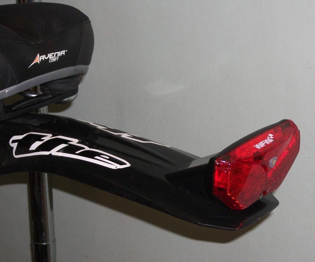
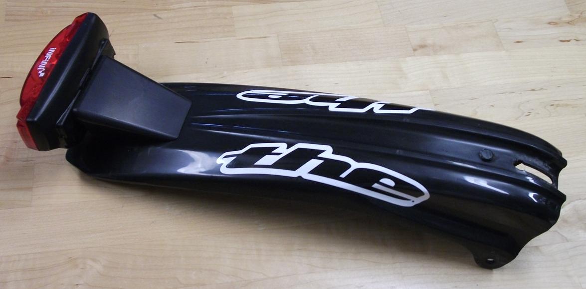
I bought a 5 led rear reflector that have a vibration sensor + a light sensor.
This one will activate by himself when its dark outside and stop after 4 min of "no vibration" activity.
Since no useful bracket came with it, I decided to make a decent one custom fit to my rear fender:
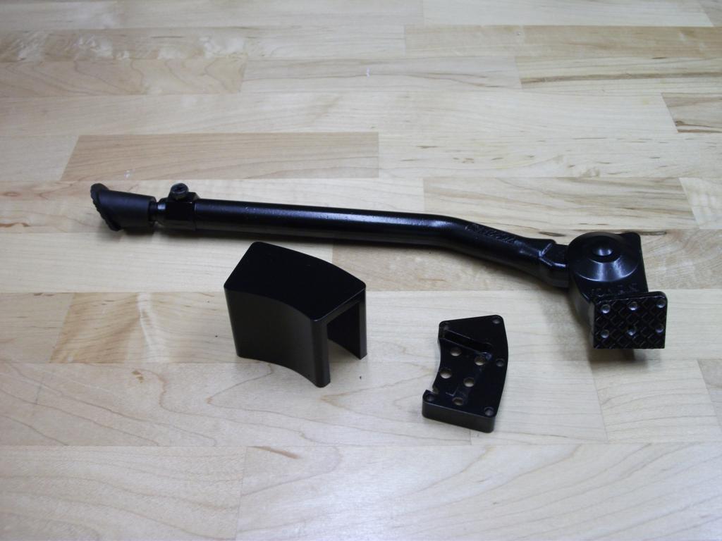
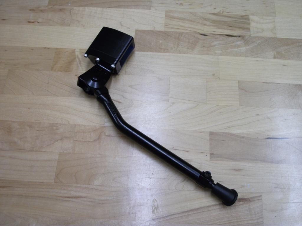
A-Line DH Kickstand:
Alu 6061-T6 black painted designed pieces with a modified 10$ kickstand.
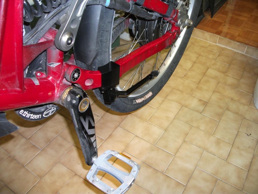
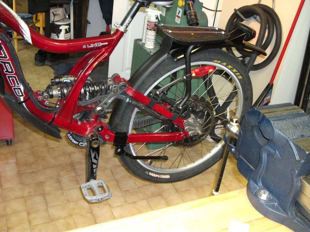
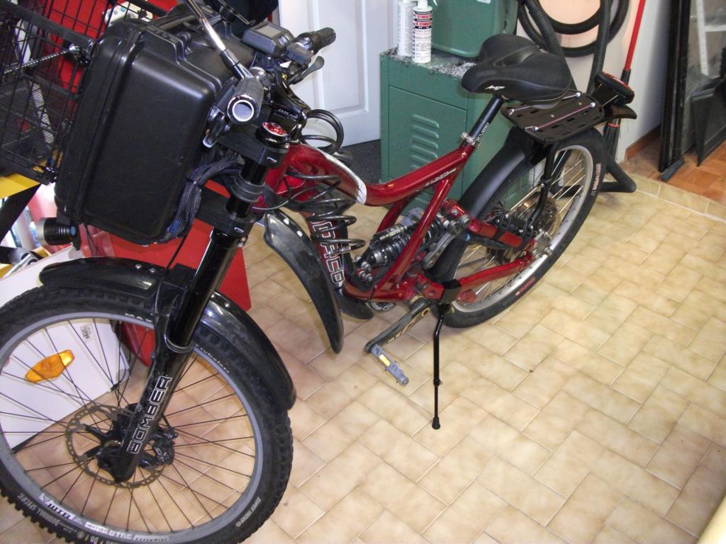
Now I basicaly added a DH kickstand designed to fit an A-Line + the rear mudguard is now acting as a mudguard.
Steering at low speed is a bit odd although I get used to it quickly. As soon as you go above 25kph, the feeling is awesome. Steering is really quick, I would compare it as driving a 400 lbs motorcycle. Pretty stable at high speed and in curves. The weight at the front prevent any chance for me to make wheeling even if I didn't increase my wheel base distance. ( controller is limited at 45 A though )
Data:
Battery pack weight : 23.4 lbs ([100.8V], 24S, 2P, 30C, 16Ah Lipo) [specific energy 130-200 Wh/kg]: http://www.hobbyking.com/hobbyking/...lightmax_8000mAh_6S1P_30C_AUS_Warehouse_.html
Bike weight with battery pack : 96.4 lbs
Bike + driver ( me @ 175 lbs ): 271.4 lbs
Max speed according to CA : 88 kph ( 55 mph ) ( Controller is limited at 45 A )
Bike: Norco A Line 2009 Park Edition, Medium frame: http://www.norco.com/archives/2009/?id=48a31c94f3e4f
Motor : Crystalyte HS3540
Controller: Lyen 150V : http://endless-sphere.com/forums/viewtopic.php?f=31&t=18605
Schlumpf drive: 34 T front, 14 T rear. High Speed Drive ( 2.5:1 ) Efficient pedaling up to 50 km/h ( 31 mph )http://www.schlumpf.ch/hp/hsd/hsd_engl.htm
Run time : average is roughly 90min @ 35 kph (22 mph). Distance = 50km ( 31 miles )
Charge time : 3hours @ 1/2C ( limited by my power supply ). It will go down to 45min @ 2C once the new charger is built.
Charge cost : 0.20$ / 100km ( 60miles )
Average of 26 WH/km @ 35 kmh (22 mph)
Average of 35 WH/km @ 50 kmh (31 mph)
Now, the development part:
I only made one E-bike before this one, but the experience I got from riding in Montreal's road at 70 kph without suspenison is ... Frightening!!!
So, this time I openned the wallet and bought a DH Norco A-Line Park Edition 2009:
The Motor is a Crystalyte HS3540:
The 2009 A-Line was chosen mainly because of its removable dropouts. The first task was to scan those dropouts on a 3D scanner then rebuild those on the CAD.
My initial goal was to make them stronger around the pivot, as well as the break attachment and add the 7.5mm per dropout to be able to fit the HS3540 in this 150mm frame.
Original dropout:
changes to be made:
Rendered result:
I have a small CNC at home, but those dropout are too big for the machine capacity. The quote to make this set was 1500$ and 520$ from two local machine shop in 6061-T6 ...
Price was just too high so I went with the plan B. (modify and re-use the old drop-out then glue or press fit an insert as Doctorbass did.)
Insert in Dormex 100 or S.S.:
Result pres fit + DP 420 epoxy:
The extra 7.5 mm is included in the insert to fit the 135mm requirement for the HS3540 motor.
Now, from CAD to reality:
Each insert was 85$ and were made from Francois G. I did the modification on the Alu dropout with my CNC and a jig that I designed.
Press fit result:
Assembly part 1:
Assembly part 2 with nut, washer and lock washer:
Assembly part 3:
The wheelbase is then exactly the same (1170mm or 46in). 22 lbs of LiPo battery at the front, 100.8v, 16Ah and the Lyen controller limit the current at 45A. This weight/current set-up prevent the front wheel from lifting.
Front box: I use a Seahorse 520 http://www.seahorse.net/se520.aspx sealed lockable box for the Front battery pack:
They also offer to modify the box cutouts if you send them a 3d drawing.
I made the box holder out of Black Delrin. The box contain 24S2P Zippy LiPo battery. 100,8V 16AH ( roughly 22 lbs ):
The battery is packaged in a 2mm foam layer and is removable by releasing 2 velcro straps ( not shown ).
Key switch + 6 pin connector for charging with protective cap + delrin holder are shown on this view.
The velcro strap anchor are bolted in the Delrin holder with a 1 1/2" bolt:
Completed battery pack ( 24S, 2P, 30C, 16Ah Lipo, 23.4 lbs)
I'm using 2mm foam around all battery.
The battery is removable as an assembly and come with the balance cable as shown below:
Battery strapped with velcro inside the box. Centered and constrained.
Charging area in the garage:
Home made charger with 4 x Turnigy 200W unit. They are connected in serie and each is powered by an isolated individual power supply. This allow me to charge without disconnecting anything.
Not having a stand is annoying, so I made a hanging support to stabilize the bike. It allow me also to remove the front wheel easily as the wheel is 1/4" above ground.
After 935km done on my initial battery pack ( 41 cycles ) charging cost is just below 2$
Of course the CA bracket didnt fit between the stems brackets... so I decided to make a stronger holder.
Material is black Delrin. Mass = 56g
Since the Seahorse box is waterproof and there is limited air flow inside, I was worried about the battery temperature inside the box.
I designed and added a holder + temperature sensor to monitor it while running. ( temperature sensor is inside, near the top of the box )
After several rides under hot and sunny days, the internal temperature never reached 40 deg C.
I also adapted the GPS holder on top of the box:
Bolted from inside the box, (sorry about the muddy picture )
Temp sensor + GPS in place:
I bought a 5 led rear reflector that have a vibration sensor + a light sensor.
This one will activate by himself when its dark outside and stop after 4 min of "no vibration" activity.
Since no useful bracket came with it, I decided to make a decent one custom fit to my rear fender:
A-Line DH Kickstand:
Alu 6061-T6 black painted designed pieces with a modified 10$ kickstand.
") I dont have much experience in bike, but I have 15 years experience doing 3D CAD design, and maybe 10 years doing CNC programing/milling/turning.
I dont have much experience in bike, but I have 15 years experience doing 3D CAD design, and maybe 10 years doing CNC programing/milling/turning.