JCG
100 W
- Joined
- Nov 10, 2008
- Messages
- 174
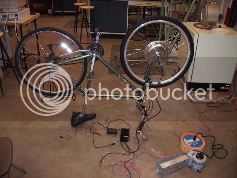
Ok, as I promised to Ypedal in the E-bike Tech thread http://tinyurl.com/5vru2k, I have fired up the digital camera and started this thread to chronicle progress (or lack thereof) for this project. Yesterday I ordered a bunch of stuff: a NineContinent kit (700c wheel, thumb throttle, Cycle Analyst, no battery) from Renaissance Bike Co., a regen-capable Kelly controller (KEB48221), lots of insulated wiring and ring terminals (8 AWG), and a big, watertight, lockable enclosure for the back of the bike. While all that stuff is on the way, I thought I could at least post pictures relating to the energy storage system: the ultracapacitors. First, let's look at a single module:
http://i400.photobucket.com/albums/pp85/jcganley/16V330F_single.jpg
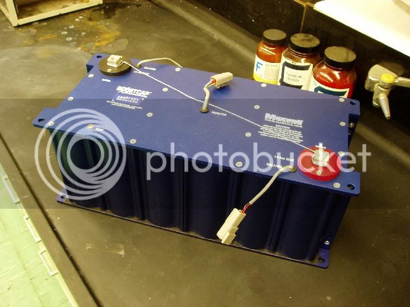
Notice I have cleverly placed some heavy metals and carcinogens in the photo to show how tough I am. Just to keep the gearheads and Edisons in the crowd from laughing at the Chem E.")
This thing is rated at 330 F and 16 V. It's made up of six ultracap cells in series (each 2000 F and 2.7 V). It can store about 42 kJ of energy and weighs about 4.5 kg (10 lbs). To reach a voltage closer to the kind used by the hub motor (36 V), I'll connect two modules in series:
http://i400.photobucket.com/albums/pp85/jcganley/16V330F_dual.jpg
I could add a third module (I have one) to make 48 V, but I'd be better off just using this 18-cell behemoth:
http://i400.photobucket.com/albums/pp85/jcganley/48V160F.jpg
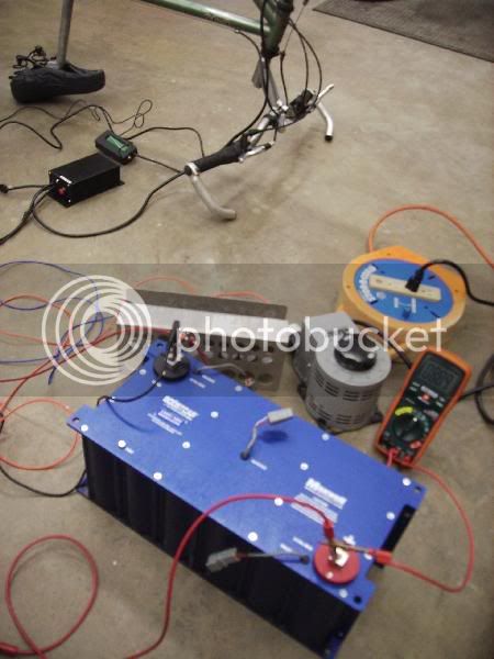
Rated at 48 V and 140 F, it is probably more juice than I need (and weight too)... but it'll still fit in my enclosure if I get adventurous. I accomplish my charging in the lab setup by using a variac through a 20 A bridge converter:
http://i400.photobucket.com/albums/pp85/jcganley/variac_bridgerect.jpg
I slowly increase the transformer voltage to the rectifier to keep the charging current at about 5-10 A. Here is the setup before charging:
http://i400.photobucket.com/albums/pp85/jcganley/no_charge.jpg
Notice here I've connected the cell balance cables, but I won't want to do this while charging in the lab, as there's a sink of about an amp during charging. It's not recommended to use the balancer unless you're charging with at least 18 A (more than the variac can handle). Halfway charged:
http://i400.photobucket.com/albums/pp85/jcganley/charging_halfway.jpg
And full charge:
http://i400.photobucket.com/albums/pp85/jcganley/full_charge.jpg
Note that the variac is off, the caps are holding their charge. It was at about this time that I realized I had no way of safely discharging these things. I reacted instictively and started electrolyzing some water:
http://i400.photobucket.com/albums/pp85/jcganley/electrolysis.jpg
Hydrogen generated on the left (-), oxygen on the right (+). Don't try this at home, kids. I could have filled the whole room up with an explosive mix if I didn't have great ventilation in the lab.
I hope this first cut was enjoyable, I'll post more when parts begin to arrive. Certainly, I should be able to use this setup to test motor/controller/throttle coordination and possibly using the motor as a generator all while monitoring cap voltage and current. Also sorry to paste links rather than the pictures directly, this website was snipping off the right third of the photos. Thanks to all of you for your help and advice so far. I'm not done asking for it by a long shot...
http://i400.photobucket.com/albums/pp85/jcganley/16V330F_single.jpg
Notice I have cleverly placed some heavy metals and carcinogens in the photo to show how tough I am. Just to keep the gearheads and Edisons in the crowd from laughing at the Chem E.
This thing is rated at 330 F and 16 V. It's made up of six ultracap cells in series (each 2000 F and 2.7 V). It can store about 42 kJ of energy and weighs about 4.5 kg (10 lbs). To reach a voltage closer to the kind used by the hub motor (36 V), I'll connect two modules in series:
http://i400.photobucket.com/albums/pp85/jcganley/16V330F_dual.jpg
I could add a third module (I have one) to make 48 V, but I'd be better off just using this 18-cell behemoth:
http://i400.photobucket.com/albums/pp85/jcganley/48V160F.jpg
Rated at 48 V and 140 F, it is probably more juice than I need (and weight too)... but it'll still fit in my enclosure if I get adventurous. I accomplish my charging in the lab setup by using a variac through a 20 A bridge converter:
http://i400.photobucket.com/albums/pp85/jcganley/variac_bridgerect.jpg
I slowly increase the transformer voltage to the rectifier to keep the charging current at about 5-10 A. Here is the setup before charging:
http://i400.photobucket.com/albums/pp85/jcganley/no_charge.jpg
Notice here I've connected the cell balance cables, but I won't want to do this while charging in the lab, as there's a sink of about an amp during charging. It's not recommended to use the balancer unless you're charging with at least 18 A (more than the variac can handle). Halfway charged:
http://i400.photobucket.com/albums/pp85/jcganley/charging_halfway.jpg
And full charge:
http://i400.photobucket.com/albums/pp85/jcganley/full_charge.jpg
Note that the variac is off, the caps are holding their charge. It was at about this time that I realized I had no way of safely discharging these things. I reacted instictively and started electrolyzing some water:
http://i400.photobucket.com/albums/pp85/jcganley/electrolysis.jpg
Hydrogen generated on the left (-), oxygen on the right (+). Don't try this at home, kids. I could have filled the whole room up with an explosive mix if I didn't have great ventilation in the lab.
I hope this first cut was enjoyable, I'll post more when parts begin to arrive. Certainly, I should be able to use this setup to test motor/controller/throttle coordination and possibly using the motor as a generator all while monitoring cap voltage and current. Also sorry to paste links rather than the pictures directly, this website was snipping off the right third of the photos. Thanks to all of you for your help and advice so far. I'm not done asking for it by a long shot...