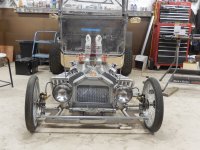
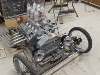
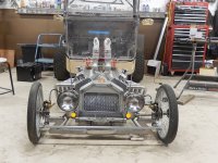
C Cab Hot Rod Power Advice

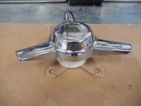
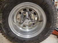
Bling! Day!

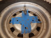
Set about making a templet for the spinner.

Double layered tape for finding hole spacing
DSCN5191.JPG

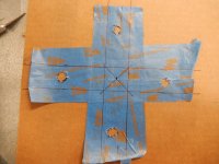
Transfering to cardboard

DSCN5192.JPG

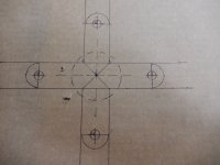
Verifying and making measurements exact

DSCN5195.JPG

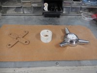
Template cut and checked for fit, centerpiece mock-up cut, and verified for offset.

DSCN5200.JPG

Tomorrow I hope to turn this template into a metal adapter bracket.

DSCN5197.JPG
 
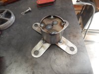
Step One

DSCN5202.JPG

Step Two
DSCN5203.JPG

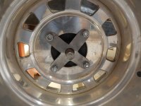
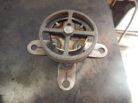
Step Three - minus the crossbar that will hold the spinner threaded ring
DSCN5206.JPG

Step four - A sneak peek
DSCN5204.JPG
 
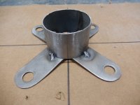
OK, this project is complete.

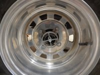
Just a couple more pics of how I secured the center portion.
Not shown is the nut that I welded on the reverse side of the inner plate.

DSCN5207.JPG

I screwed in stop screws after this photo was taken.
It's needed to keep the ring from turning when trying to unscrew the spinners.

DSCN5208.JPG
 
It has been a while since we worked on getting my electrical for the motors so I understood it enough to wire it up.
With good results, I must add.

Now as I get closer to completion, (tear down and detailing) I am starting to think about the 12v volt system.
I seemed to have regressed in my understanding a wee bit, so I sure could use your help once again.

I'm getting a suggestion that would alter the latest wiring schematic that we made.
Another suggestion was that the way we have it wired the voltmeter will only show the twelve volts,
never the battery voltage, which is what I want.

I will be adding this into the mix as well.
https://www.ebay.com/itm/272682216991?ssPageName=STRK%3AMEBIDX%3AIT&_trksid=p2060353.m2749.l2649

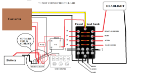
The suggestion wants to add a relay. Because I'm still not comfortable with all this electrical stuff,
I can't fathom why. Based on our latest schematic.

Here is the link to the suggested change.

https://postimg.cc/jCLWfR5C

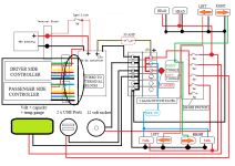
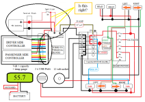
And here is a reminder of the last schematic we worked on.

StreetRunner wiring diagram.png

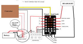
We also talked about this setup. But don't see that in the final schematic above.

Without relay

converter - fuse - no relay.png

With relay
converter - fuse - relay.png
 
Your original diagram looks good. I don't see the need for a relay there. Your dc-dc has a low current on/off line so it acts like a relay.
The negative connections on the fused load bank should be all tied together so it doesn't matter which ones you use or don't use.

I'd suggest having a voltmeter that reads the main pack somewhere, as this is much more important than the 12v. You could have both. I've seen some inexpensive ones that show the voltage and also the calculated state of charge (like a fuel gauge).
 
fechter said:
It's very hard to perfectly center a hole on a large piece. I suck at it. At least chains have some forgiveness if you run them a little loose.

the only surefire way i know to do it is chuck it in a lathe held by its outer edges and put the drill bit in the workpiece end holder and run that into the center of the spining piece you're working.

if you don't have a movable end holder you can just use the toolholder to use a tool to carve out the hole in the middle.


and if i were you i'd add at the least osme of those 1 inch foil backed foam sheets gbetween the cieling rafters/joists/etc, and then on all the walls. it'll make a significant difference to the heat in there. the more you can put on the cieling hte better; if you can't use the foot-thick rolls of insulation then a few sheets would be better than nothing.
 
Morning fechter

I do have a voltage gauge like this. I haven't quite got to the point of where it will go.
https://www.amazon.com/Battery-Capacity-Indicator-Lead-Acid-Motorcycle/dp/B07V2KMQGQ/ref=asc_df_B07V2KMQGQ/?tag=hyprod-20&linkCode=df0&hvadid=366343882692&hvpos=&hvnetw=g&hvrand=324040631748061352&hvpone=&hvptwo=&hvqmt=&hvdev=c&hvdvcmdl=&hvlocint=&hvlocphy=1013549&hvtargid=pla-796190987249&psc=1&tag=&ref=&adgrpid=76503872296&hvpone=&hvptwo=&hvadid=366343882692&hvpos=&hvnetw=g&hvrand=324040631748061352&hvqmt=&hvdev=c&hvdvcmdl=&hvlocint=&hvlocphy=1013549&hvtargid=pla-796190987249
 
amberwolf said:
and if i were you i'd add at the least osme of those 1 inch foil backed foam sheets gbetween the cieling rafters/joists/etc, and then on all the walls. it'll make a significant difference to the heat in there. the more you can put on the cieling hte better; if you can't use the foot-thick rolls of insulation then a few sheets would be better than nothing.

The remaining insulation does need to be completed. With the addition of the swamp cooler, it has seemed less of a priority.
As far as the ceiling goes, I haven't decided just how I want to complete that. With the hoist, lights, wiring, just not sure. Foam board or glass fiber.
 
Just_Ed said:
Morning fechter

I do have a voltage gauge like this. I haven't quite got to the point of where it will go.
https://www.amazon.com/Battery-Capacity-Indicator-Lead-Acid-Motorcycle/dp/B07V2KMQGQ/ref=asc_df_B07V2KMQGQ/?tag=hyprod-20&linkCode=df0&hvadid=366343882692&hvpos=&hvnetw=g&hvrand=324040631748061352&hvpone=&hvptwo=&hvqmt=&hvdev=c&hvdvcmdl=&hvlocint=&hvlocphy=1013549&hvtargid=pla-796190987249&psc=1&tag=&ref=&adgrpid=76503872296&hvpone=&hvptwo=&hvadid=366343882692&hvpos=&hvnetw=g&hvrand=324040631748061352&hvqmt=&hvdev=c&hvdvcmdl=&hvlocint=&hvlocphy=1013549&hvtargid=pla-796190987249
That looks like the one I have. Perfect.
The % charge will give low readings when you are discharging, but will be fairly accurate when you stop for a while. The voltage reading will always be right. The main thing is to avoid over discharging your pack.
 
fechter said:
That looks like the one I have. Perfect.
The % charge will give low readings when you are discharging, but will be fairly accurate when you stop for a while. The voltage reading will always be right. The main thing is to avoid over discharging your pack.

I want to get the car out for an extended drive to see how far/long of a drive that battery package will give me.

Still looking for a GPS app for the wife's iPhone. The first one wouldn't pick up the GPS signal.
I would invest in one of the stand-alone models, but I'm afraid, even they won't pick up the signal.
 
fechter said:
Just_Ed said:
Morning fechter

I do have a voltage gauge like this. I haven't quite got to the point of where it will go.
https://www.amazon.com/Battery-Capacity-Indicator-Lead-Acid-Motorcycle/dp/B07V2KMQGQ/ref=asc_df_B07V2KMQGQ/?tag=hyprod-20&linkCode=df0&hvadid=366343882692&hvpos=&hvnetw=g&hvrand=324040631748061352&hvpone=&hvptwo=&hvqmt=&hvdev=c&hvdvcmdl=&hvlocint=&hvlocphy=1013549&hvtargid=pla-796190987249&psc=1&tag=&ref=&adgrpid=76503872296&hvpone=&hvptwo=&hvadid=366343882692&hvpos=&hvnetw=g&hvrand=324040631748061352&hvqmt=&hvdev=c&hvdvcmdl=&hvlocint=&hvlocphy=1013549&hvtargid=pla-796190987249
That looks like the one I have. Perfect.
The % charge will give low readings when you are discharging, but will be fairly accurate when you stop for a while. The voltage reading will always be right. The main thing is to avoid over discharging your pack.

I hooked up the voltmeter directly to the battery pack. It read the same as the one incorporated into the battery pack. So I guess we're a go for using that.

I'm working on relocating the converter to another location.
Its present location behind the battery is inconvenient.

The hardest part of this project is the design and do, part.
If only it was like a puzzle, and you need to find the right piece and fit it in.

I have to think about design, what I want to do, how am I going to do it, can it be done, am I able to do it, etc.

Ok, I've got all that figured out. Now I'm too tired to do it !
 
Looking at the area where the ignition switch is, has me confused.

Either I don't get it or there's something wrong. Which is it?

To me, there are two positive lines going to the converter.
One line switched and the other line direct.

Also notice that I have rewired the voltmeter to come directly from the battery/switched.
The wires are not drawn in to minimize confusion.

With the battery breaker 'on', isn't the line to the converter 'hot' all the time?
And only the line to the motor controllers is switched :confused:

StreetRunner wiring diagram -2.png
 
I think the dc-dc wiring looks right. One line is always hot and the one going to the ignition turns it on/off. Something similar should be going on with the controllers. There should be a fat red wire from the controllers that stays always on going to the battery and a skinny wire (ignition) that goes to the ignition switch. The idea is the skinny wires don't take a lot of current so the ignition switch doesn't need to be huge. The switching is done inside the controller and dc-dc. The main breaker (which I don't see in the diagram) should disconnect everything coming off the battery. You can leave this on all the time normally, but would be good to turn off if you are storing it for a long time.

The battery meter can come off the ignition switch so it turns off with the key.

You could have the controllers main power lines switched by the ignition switch, but the switch would need to handle the full current and would need to be huge. This is not how it is done normally.
 
Depends on the way your converter is made. If it has two (red) battery positive wires coming out of it, then the supply wire goes to battery, and switch wire goes to ignition.

If it only has one battery positive wire coming out of it, then:

If you intend the converter and anything it runs to only work if the ignition is on, then the converter should only get power from the switch.

If you intend the converter and anything it runs to work anytime the battery is switched on, even if the controllers are deactivated, then the converter should get power directly from the non-battery side of the battery switch.


Typically in my own systems, I wire the lighting (and any converters that run it, since mine have only had one power wire) to be powered anytime the battery breaker is switched on, so that I can use it roadside to work on tire/wheel/motor/controller/etc problems, even though the whole traction system may be turned off at the keyswitch.

On CrazyBike2 this was all direct-wired. On SB Cruiser this is all done with automotive relays (that have built-in 30A fuseholders, so I don't have to remember what fuse goes to what section of the trike).

The actual power to controllers/etc is not switched except at the battery breaker, but the keyswitch/ignition line to the controllers *is* switched by a relay.

If I need to I can even just pull the fuse to kill the controllers without switching the ignition off, so the Cycle Analyst/etc is still powered on and monitoring, but the controllers can't operate the motors and jerk the trike around, such as if I'm troubleshooting a throttle problem or a PAS problem and need to know when those are working right without having the motors go WHEEEEEEE. ;)
 
Getting near time to put lights on this project.

I've been scouring the internet, trying to find light assemblies that won't cost me the price of this whole project. I find there are virtually two sizes available in the bullet style, I want. 7" and 5 3/4" diameters.

I ordered a set of 7" but canceled it soon after because I thought they would be too large.

https://www.speedwaymotors.com/Chrome-Dietz-Type-Headlights-Standard-Bulb,2948.html

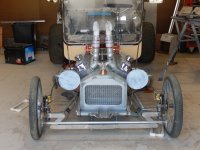
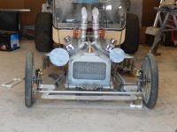
I have cut out mockups to add visualization.
Don't look too close at the light position. They are held on with tape and magnets.
But you get the idea.
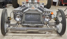
With the mockups, they are OK I suppose. Hot rods of the past have often had oversized lights.
It gives it a cartoonish look, which is OK with me. It adds character.

DSCN5216.JPGDSCN5217.JPG

Also made a 5 3/4" size to match up against the 7".
They come primarily as motorcycle size lights.
DSCN5218.JPG
 
It can see!, It can see!

Can't you see the personality of this car starting to emerge?

Just in mockup form. Next to make the brackets permanent.
DSCN5223.JPG
DSCN5224.JPG

Had one small issue with clearance for the drag link. But solved.
Also had to rotate the brake line banjo fittings so the hose wouldn't rub on the light bucket.
DSCN5225.JPGDSCN5226.JPG

Next I must put thought to where and what type of front turn signals to mount.
 
Thanks for the idea and links.

I'm wanting to try and complement the look of the headlights.
I will be painting the black part of the headlights to red, matching the rest of the car.
I thought maybe doing the same with the turn signals. But they may stay chrome because of the size.

DSCN5225 with turn signals.jpg

Something like this might work. With their low profile, they may fit just right in the locations I've indicated.

https://www.ebay.com/itm/165116054426?_trkparms=amclksrc%3DITM%26aid%3D1110006%26algo%3DHOMESPLICE.SIM%26ao%3D1%26asc%3D234518%26meid%3D80f47638a99c4f0192c0d5a008de4ec8%26pid%3D101195%26rk%3D6%26rkt%3D12%26sd%3D263763889320%26itm%3D165116054426%26pmt%3D1%26noa%3D0%26pg%3D2047675%26algv%3DSimplAMLv9PairwiseWithPLXWeb&_trksid=p2047675.c101195.m1851&amdata=cksum%3A16511605442680f47638a99c4f0192c0d5a008de4ec8%7Cenc%3AAQAGAAACACfttPC6WLwY0P0IrVRjnncAP%252BKwdELSX4R4UACWgiQFyAOnBP95MGb9Tv58pzKtsIAQpqrMX1km1D3lNzEkm%252BRR4PhEF3YikqKIjBF%252FMKED4msiqAqFKO0ilPvemb699MOvIcjbS%252BdmI8%252BkNyFeevq8MJ%252Bn9iJaXhLUw9OMl3PeCxwY8xI5sD%252B1npe5gLthCpG9urEgxI%252BSX3rKV%252BCVMTNJWi9CEDCsbPbutXED0lo%252FxOMpFT%252FYu1hABXb7GdRTakihu2JniV7TviQgigiK1mqIAHF28ZilBVRHv6GlFc0od7WiFawMLkQJYOmDzdVRH1WMc5LZaPNgYlMmNk2%252FerC4HtUPslSORx%252FXmf3I922ZJuVX87BtDMUdF7ICUoIjqbUqt%252BinC9mJGBMEsNcCQ5n%252BqK8F8m%252F%252F4LW7vRZBr1jVBlk%252BOmeLRS3pD3UgFwKDyIm00%252FGmMvEVkYp4hYXtYS1FM2TnHYho%252BInw3aPnvIW2l2aC8WKckyd9NP4GdUbdmFJmhKXJqLdbe2TVwBhOXOkgrc%252FJnwABiYGzutEoz5B8zGkoRbwNRO7WZLciDM3LMHsMIdXeTjtjkRQGpNn7UqMe5gBn39Z0A7GfuQrRRybaV7t9qGm2F%252BkCTkNFT%252F6x4nGUnYudkRaVxncOCuzh1a0EcSI7f3ISgmtKZ9VbHX04%7Campid%3APL_CLK%7Cclp%3A2047675
 
Back
Top