Sinusoidal wave brushless motor controller

fany

10 W
Joined
Jun 9, 2009
Messages
70
People complained KEB/KBS generated terrible noise at the starting-up,especially for hub motor.Because most of hub motors are based on sinusoidal waveform.But KEB/KBS is based on trapezoidal waveform control.That is why there is a noise for the combination of KEB/KBS controller and hub motor or spoked motor.
KLS controller is still supposed to work with sensored BLDC motor controller.The BLDC motor is based on three hall sensors.
Using fast SVPWM and FOC to achieve very high efficiency.
The user program is App type.
The APP software is based on Tablet with Android OS.A Z-TEK USB cable is required to do Auto_Identify function to drive the motor.Z-TEK USB cable is popular in Android OS Marketing.People can get it locally and easily.And customers complained the user program based on Win OS can not be connected well.This problem will not happen on Android OS.The updating frequency for Win OS is too fast.To be honest,we can not catch up it.

The different motors have different features and parameters.People need to do a auto_Identify to update all the related parameters in the controller to match the motor you are using.People don't have to try 36 combinations one by one to find the correct one to run the motor.
 
I have the KLS7230S together with HT3525 in my bike.

The motor is very quiet, only the wheels on the street make noises.
With this motor and 20S LiPo 60km/h are reached very quick.

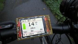
The Android APP shows infos while driving, so I tried to recive these values (Speed, voltage, current....) over the Serialport and show them on the bikecomputer.
And it works :)

k-WP_20150824_07_22_00_Pro.jpg

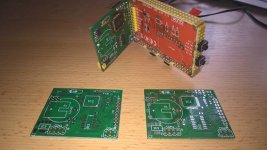
There will be a housing for the computer soon :)
*edit*
View attachment 1
k-WP_20150831_07_26_52_Pro.jpg
*edit end*

If someone is interested in PCB layout or code I can upload it.

I am very happy with the KLS, good work Kelly ;)
 
Hi tuxadmi.
Could you share what you learned about the serial protocol used by the KLS controllers?
I took a crack at reading the serial commands, but it doesn't look like ASCII characters are used. So before I start analyzing with the oscilloscope I thought I just ask you about it. It looks like 19200 baud is used, but that's as far as I've gotten so far.
 
fany said:
People complained KEB/KBS generated terrible noise at the starting-up,especially for hub motor.Because most of hub motors are based on sinusoidal waveform.But KEB/KBS is based on trapezoidal waveform control.That is why there is a noise for the combination of KEB/KBS controller and hub motor or spoked motor.
KLS controller is still supposed to work with sensored BLDC motor controller.The BLDC motor is based on three hall sensors.
Using fast SVPWM and FOC to achieve very high efficiency.
The user program is App type.
The APP software is based on Tablet with Android OS.A Z-TEK USB cable is required to do Auto_Identify function to drive the motor.Z-TEK USB cable is popular in Android OS Marketing.People can get it locally and easily.And customers complained the user program based on Win OS can not be connected well.This problem will not happen on Android OS.The updating frequency for Win OS is too fast.To be honest,we can not catch up it.

The different motors have different features and parameters.People need to do a auto_Identify to update all the related parameters in the controller to match the motor you are using.People don't have to try 36 combinations one by one to find the correct one to run the motor.

KLS controller can support PC software and Android Tablet App now.There is one more choice for customers to program the controller KLS now.
 
The PC software does not work on my Win10 version. I get Software version does not match, please use the latest software.

I have now played a little with the RS232. It seems to be using very simple 8 bit binary strings. To make it easy the phone software lists the everything in the same order as the data is sent from the controller.
I have not played with anything other than the monitor section yet.
Sending:
Code:
3A 00 3A
returns somthing like:
Code:
3A 10 2D 05 00 00 00 00 01 00 00 3B 00 0E 00 00 00 00 C6
to explain I'll give the 8bit groups individual numbers:
Code:
00 01 02 03 04 05 06 07 08 09 0A 0B 0C 0D 0E 0F 10 11 12
3A 10 2D 05 00 00 00 00 01 00 00 3B 00 0E 00 00 00 00 C6
00 seems to be identifying the code sent. If i call 3A 00 3A it returns 3A. If I call 3B 00 3B it returns 3B.
01 I have no idea what this is. It has always been 10 when I've tested.
02 Throttle
03 Brake pedal (not confirmed)
04 Brake switch (not confirmed)
05 Foot switch (not confirmed)
06 Forward switch (not confirmed)
07 Reverse (0 or 1)
08 Hall switch A (0 or 1)
09 Hall switch B (0 or 1)
0A Hall switch C (0 or 1)
0B B+ Voltage
0C Motor Temp (not confirmed)
0D Controller temperature (I think it is Celsius, but it is very off and low res)
0E Setting Dir (0 or 1)
0F Actual Dir (0 or 1)
10 Marked as reserved.
11 Marked as reserved.
12 I have not found out what this is. It might be a checksum.

Not confirmed means that my controller does not support the function or I have not connected the correct switch or sensor yet.

Sending:
Code:
3B 00 3B
returns a similar string as 3A 00 3A
04 and 05 makes up the motor speed
07 is the phase current. I guess 06 also, but I haven't tried >255 amps to see if 06 changes.
The rest of the 3B string and the 3C string is unknown to me.
 
Awesome. I'm about to get one of these (but the 144V/300A one. :) I'm going to be adding it to my logger as well. :D

Do you know of any other commands besides
Code:
3A 00 3A
and
Code:
3B 00 3B
. Also, can you post a picture of what the screens of the android and/or PC software looks like?

Thanks!
 
__Tango said:
Do you know of any other commands besides
Code:
3A 00 3A
and
Code:
3B 00 3B
.

To answer my own question. I sniffed the communication between the windows app and a KLS8080I, there is a third message:
Code:
3C 00 3C
, but the data is all 00s.
 
__Tango said:
Has anyone been able to figure out the checksum algorithm yet?

Looks like it's just the low 8 bits of the sum of the data in the binary string.
Code:
3A 10 2D 05 00 00 00 00 01 00 00 3B 00 0E 00 00 00 00 C6
Add all the numbers up and it equals C6.

Here's one that ends up with a number that's larger than 1 byte:
Code:
3B	10	0	0	3	C0	0	7	0	0	0	0	0	0	0	0	0	0	15
Sum them up and it's 0115. 0x115 & 0xFF is 15.
 
I also think the request is not just
Code:
3A 00 3A
. I think it's a two byte string with the checksum. add 3A + 00, which equals 3A.
 
01050001:The 12V brake switch and motor temp sensor functions used the same port on pin1.
01050002:The 12V brake switch used the different port from motor temp sensor.pin25 is 12V brake switch while pin1 is motor temp sensor.
01060001:The 12V brake switch is pin25 while motor temp sensor is pin1.And we added the brake analog regen mode on pin2.
If the software version is below 0105,there is no frequency to be chose between 10KHz and 20KHz.The Max Output fre can not be configured also.
The lastest one 0106 version will be released next month.People can read software version for each controller in the first picture of user program.
Just let people know we added brake analog regen mode for KLS controller according to so many requests from customers.
It will be released next month.
Customers can use brake analog regen mode on the same pin2.
That is to say,the customers can not use boost function and brake analog regen mode at the same time.
There is item called Boost in the user program.When it is enabled,the pin2 will be used as boost function.
When the Boost item is not chose,the pin2 will be used as brake analog regen mode.
The software version 0106 can support this brake analog regen mode.
But it must be the new controllers.The controller KLS can not support reflashing operation.

KLS8080I is designed for the motor with common three hall sensors.
KLS8080IPS is designed for the motor with sine/cosine speed sensors.
You can find the details in configuration in KLS8080I/IPS user manual.
When speed sensor type is at 4 for linear hall sensor(sin/cosin speed sensor),you need to use KLS8080IPS controller.
For example,we can provide Mars 1115 motor with sin/cosin speed sensor.
There are +5V,GND,Sin and Cosin port from this speed sensor.
We have already provided many KLS-8080IPS and ME1115 motors for customers.
 
Here is the correct operation steps for identification angle function.

It is for 8080I/IPS controller.
1,Please connect 12V-24V to pin7 and pin6.Pin7 is positive and pin6 is GND.
pin7 and pin6 is the isolated power supply for KLS-8080I/IPS controller.

2,Please connect the motor phase cables to U,V,W.Please connect hall sensors connector to the controller.

3,Please connect the batteries to B+ and B- of the controller.

4,Please connect the throttle wires to the motor controller.

5,Please connect the USB cable and 4pin connector to RS232 converter between controller and user program.

6,Please double click the KLS user program.

7,You will see the first picture of user program.

8,Please read the identification angle value.It is good if it is at 85.

9,Please fill 170 in the identification angle item.And please click the write button.Please turn off the power supply.

10,Please turn on the power supply after the power supply is off for a few seconds.The controller will send a constant beep sound.If you get a KLS-S controller,the LED will be solid on in this case.

11,Please wait about 2-3 minters.

12,If the identification is finished,the constant beep sound or solid Red LED will be disappeared.And you will see reset error in the monitor screen.

13,Please turn off the power supply again.Please wait about a few seconds to turn on the power supply again.

14,You will see 85 in the identification angle item.That is to say,the controller identification angle operation is successful.You can use the controller to drive the motor now.

15,If the constant beep sound last above 5 minters,please return the first picture of user program.Please write 85 instead by manual.
Please don't keep 170 in the identification angle item in this case.
And please turn off the power supply in this case.
Please try again from step 6.

16,Please don't keep 170 in identification angle item before power supply is turned on after the identification operation is successful.


It is for KLS-S/D controller.
1,Please connect Battery Voltage for pin7 and B+/B-.

2,Please connect the motor phase cables to U,V,W.Please connect hall sensors connector to the controller.

3,Please connect the batteries to B+ and B- of the controller.

4,Please connect the throttle wires to the motor controller.

5,Please connect the USB cable and 4pin connector to RS232 converter between controller and user program.

6,Please double click the KLS user program.

7,You will see the first picture of user program.

8,Please read the identification angle value.It is good if it is at 85.

9,Please fill 170 in the identification angle item.And please click the write button.Please turn off the power supply.

10,Please turn on the power supply after the power supply is off for a few seconds.The controller will send a constant beep sound.If you get a KLS-S controller,the LED will be solid on in this case.

11,Please wait about 2-3 minters.

12,If the identification is finished,the constant beep sound or solid Red LED will be disappeared.And you will see reset error in the monitor screen.

13,Please turn off the power supply again.Please wait about a few seconds to turn on the power supply again.

14,You will see 85 in the identification angle item.That is to say,the controller identification angle operation is successful.You can use the controller to drive the motor now.

15,If the constant beep sound last above 5 minters,please return the first picture of user program.Please write 85 instead by manual.
Please don't keep 170 in the identification angle item in this case.
And please turn off the power supply in this case.
Please try again from step 6.

16,Please don't keep 170 in identification angle item before power supply is turned on after the identification operation is successful.
 
Hi. Any news about serial communication? We need realtime communication in usable form! This is real killer feature Fany. Any android prohne can be cycle analyst.
 
snejky said:
Hi. Any news about serial communication? We need realtime communication in usable form! This is real killer feature Fany. Any android prohne can be cycle analyst.

What type of realtime communication are you looking for?
 
Hi. Tuxadmi shows communication with microcontroller few post's before . I need something like: sent this string RS232 over Bluetooth and kelly responds this string.(voltage, phase, battery current...) I have some useful communion specs from Fany. We can share some knowledge. I'm arduino fan, so this feature is really good for all of us. Sorry for my bad English.
 
I have a KLS7218 that I want to hook up with an adruino via rs232.
Anyone who already tried this and has some example code?
 
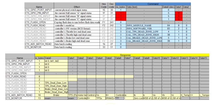
using documentation available around and documwntation from Kelly, I was able to build this table:
comandi-new.png


It summarizes all serial commands I am aware of.
I didn't start experimenting yet, anyway I'm going to do that using an ESP32 module rather than an arduino, as it has builtin wifi, bluetooth and 4MB RAM, so it should be able to perform local logging, realtime connection to smartphone over bluetooth, and remote logging over wifi using smartphone tethering.
Some ESP32 dev boards even come with sd card slot, display and battery holder.

But maybe we should move to a specific thread with a specific title.
 
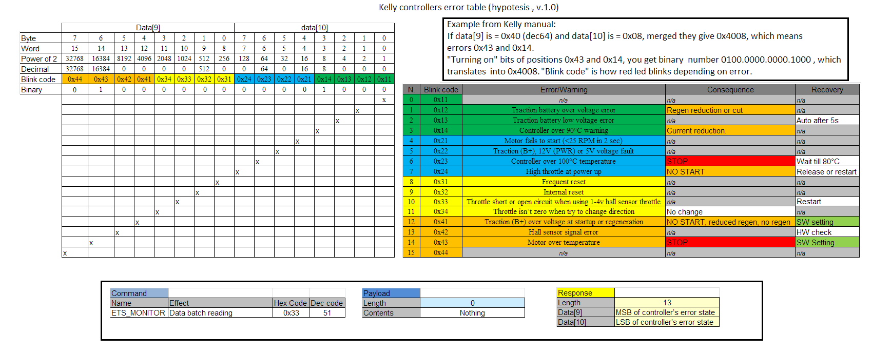
I also tried decoding the error codes, I obtained this picture:
1524795894.png


This BASIC source decodes the raw data into human readable error messages (if above picture is right):
Code:
Sub conv(Data9Data10)

Dim ErrorText(15)

Dim ErrorNum(15)

​

ErrorText(0) = "n/a 1"

ErrorText(1) = "Trac­tion battery over vo­ltage error"

ErrorText(2) = "Trac­tion battery low vol­tage error"

ErrorText(3) = "Cont­roller over 90°C war­ning"

ErrorText(4) = "Motor fails to start (<25 RPM in 2 sec)"

ErrorText(5) = "Trac­tion (B+), 12V (PWR) or 5V voltage fault"

ErrorText(6) = "Cont­roller over 100°C te­mperature"

ErrorText(7) = "High throttle at power up"

ErrorText(8) = "Freq­uent reset"

ErrorText(9) = "Inte­rnal reset"

ErrorText(10) = "Thr­ottle short or open circuit when using 1-4v hall sensor thro­ttle"

ErrorText(11) = "Thr­ottle isn’t zero when try to change dire­ction"

ErrorText(12) = "Tra­ction (B+) over volt­age at startup or re­generation"

ErrorText(13) = "Hall sensor signal erro­r"

ErrorText(14) = "Mot­or over temperature"

ErrorText(15) = "n/a 2"

​

ErrorNum(0) = "0x11"

ErrorNum(1) = "0x12"

ErrorNum(2) = "0x13"

ErrorNum(3) = "0x14"

ErrorNum(4) = "0x21"

ErrorNum(5) = "0x22"

ErrorNum(6) = "0x23"

ErrorNum(7) = "0x24"

ErrorNum(8) = "0x31"

ErrorNum(9) = "0x32"

ErrorNum(10) = "0x33"

ErrorNum(11) = "0x34"

ErrorNum(12) = "0x41"

ErrorNum(13) = "0x42"

ErrorNum(14) = "0x43"

ErrorNum(15) = "0x44"

​

For Index = 0 To 15

​ ​ ​ If (Data9Data­10 And (2 ^ Index)) = (2 ^ Index) Then

​ ​ ​ ​ ​ ​ ​ Error­sList = ErrorsList + vbCrLf + ErrorNum(I­ndex) + " - " + Erro­rText(Index)

​ ​ ​ Else

​ ​ ​ ​ ​ ​ ​ 'error not set, do nothing

​ ​ ​ End If

Next

Debug.Print ErrorsLi­st

End Sub
 
hi all,
i decoded the protocol for at least monitoring a kelly KLS and did a quick hack in perl. maybe works for KAC-controllers too.
reads motor speed, phase current, batt voltage, motor temperature / controller temperature (reads about 10 °C too low temperature) , hall sensors, pedal input, error status and the rest the app shows too.
i used it to monitor two KLS7230S.
i got about 12 complete datasets per second, which should be enough for most use cases (segway-style balancing anyone? dont know if its controllable fast enough :wink: ).

sample output of two datasets:
Code:
Actual Dir (0|1, 0=F,1=R) : 000
B+ Volt (0-200V) : 070
Brake Pedal (0-255) : 002
Brake Switch (0|1) : 000
Brake Switch2 (0|1) : 000
Controller Temp (0-150C) : 018
Error Status : 
Foot Switch (0|1) : 000
Forward Switch (0|1) : 000
HaLL B (0|1) : 000
Hall A (0|1) : 001
Hall C (0|1) : 000
Low Speed (0|1) : 000
Motor Speed : 560
Motor Temp (0-150C) : 058
Phase Current : 38
Reversed (0|1) : 000
Setting Dir (0|1, 0=F,1=R) : 000
TPS Pedal (0-255) : 190
Timestamp : 1523094529495
--------------------------------------------------------------------------------
Actual Dir (0|1, 0=F,1=R) : 000
B+ Volt (0-200V) : 070
Brake Pedal (0-255) : 002
Brake Switch (0|1) : 000
Brake Switch2 (0|1) : 000
Controller Temp (0-150C) : 018
Error Status : 
Foot Switch (0|1) : 000
Forward Switch (0|1) : 000
HaLL B (0|1) : 000
Hall A (0|1) : 000
Hall C (0|1) : 001
Low Speed (0|1) : 000
Motor Speed : 572
Motor Temp (0-150C) : 059
Phase Current : 38
Reversed (0|1) : 000
Setting Dir (0|1, 0=F,1=R) : 000
TPS Pedal (0-255) : 200
Timestamp : 1523094529570

script and notes/more samples are here: https://www.dieseltreter.de/kellycontroller-monitor-kls/ .

maybe the decoding is useful for other projects .. i am curious what will be done with it :wink:
not decoded yet: reading configuration, writing configuration (writing may be dangerous .. for example the serial number can be changed this way too as i found out by coincidence :wink: ).

cheers,
david
 
Hi all,
I know, this thread is quiet old but it helped me a lot and I want to contribute a little. Maybe it helps someone.
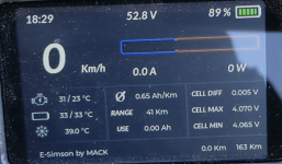
I made my own display for my electric moped conversion (electric simson) and I am able to read all data from my kelly controller (rpm/speed, voltage, current, temperature etc.) and from my daly BMS (current, voltage total, cell voltage, temperature etc).

Unbenannt.PNG
Youtube: Display running on my E-Simson


I uploaded the code on github (decode kelly controller and daly BMS communication protocol):
I am not a great programmer but the code works.
 
Hi all,
I know, this thread is quiet old but it helped me a lot and I want to contribute a little. Maybe it helps someone.
I made my own display for my electric moped conversion (electric simson) and I am able to read all data from my kelly controller (rpm/speed, voltage, current, temperature etc.) and from my daly BMS (current, voltage total, cell voltage, temperature etc).

View attachment 341289
Youtube: Display running on my E-Simson


I uploaded the code on github (decode kelly controller and daly BMS communication protocol):
I am not a great programmer but the code works.
Well done. Is the LGFX display also the microcontroller for communicating with the BMS and controller?
 
Back
Top