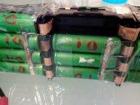
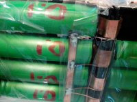
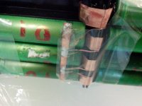
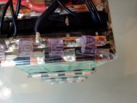
One more no “solder”, no tools, no skills, 18650 pack build.

TheBeastie said:
Looking good, so are you planing to put it in a EM3 battery frame bag? or something more fancy? I was thinking frame bag would be pretty practical for it.
They will be transparently shrink wrapped with PVC. They will go into moped "tank" (box) :D
mistercrash said:
This is cool, if the cells can be held in place so they don't pop out or move too much it is pretty sweet and soooo simple. Can you please post the exact measurements of one 4P holder with the cells and copper installed? I'm curious to figure out how big a 20S16P battery made like that would be.
They will be held additionally with capton tape and transparent PVC shrink. Holder size 7.8x8x2.6cm
www.recumbents.com said:
Any thoughts about using gold leaf between the battery and the (cleaned!) copper tab to prevent oxidation and improve the conductivity in these no-weld/no-solder packs? I think gold leaf is pretty inexpensive at the hobby store.

-Warren
Good idea, but I have grease for now, maybe later. :)
 
999zip999 said:
I like a gasket on the pos. end to add protection from the neg. case. A simple doughnut.
I do not know what type of gaskets PFs or MG1 are coming with, but definitively if they are plastic, additional paper (cardboard) gaskets are a good investment.
Thanks for all your suggestions guys! :D
 
parabellum said:
mistercrash said:
This is cool, if the cells can be held in place so they don't pop out or move too much it is pretty sweet and soooo simple. Can you please post the exact measurements of one 4P holder with the cells and copper installed? I'm curious to figure out how big a 20S16P battery made like that would be.

They will be held additionally with capton tape and transparent PVC shrink. Holder size 7.8x8x2.6cm

Thanks parabellum, sadly it would end up being just a bit too bulky for my scooter.
 
mistercrash said:
parabellum said:
mistercrash said:
This is cool, if the cells can be held in place so they don't pop out or move too much it is pretty sweet and soooo simple. Can you please post the exact measurements of one 4P holder with the cells and copper installed? I'm curious to figure out how big a 20S16P battery made like that would be.

They will be held additionally with capton tape and transparent PVC shrink. Holder size 7.8x8x2.6cm

Thanks parabellum, sadly it would end up being just a bit too bulky for my scooter.
Sorry for the confusion 2.6cm is with contactor pin unbend. With bend or cut off pin LWH 78mmx80mmx21,5mm, but cell is sitting 1,5x mm inside the holder and you can trim it down to 20mm.
 
Very impressive. Science at work. Best of luck! 8)
I just turned 45 and I can still ride my regular bicycles, but I ride my electric bicycles a lot more... and I hope I can still ride when I'm way into my 60s. Dogman told me a few weeks ago that most of the people that buy the companies kits he works for are mostly in their 60s and beyond.
 
Our local shop was surprised when someone my age was interested. I look about 40.


I'm back n forward on the gold leaf idea. Gold is a poor power connection, because any arcing and it's gone. It's for signals. However arcing should be rare, and could work as soldering. Ensuring it won't happen again, while remaining a mechanically weak connection so you can still retrieve the cells easily.

The connection causing heat is my only concern. Anything other than fire is a fair result. Fire is terrible. I bet many flashlights use an 18650 with spring connections though and take a few amps. There must be benchmarks their to see.
I had envisioned these 4p blocks supplying around 20 amps, so just 5 amps each. I think enough material is present to soak up a bit of heat. At 10 amps per cell it is getting interesting though. Thankfully a resistive connection can push the power a different direction, but fully loaded the cells will be less happy to take on any more, raising there resistance. Thermal runaway like processes could occur. I think a safety margin might help. Perhaps pull just 75% of the full C rating, so a cell/connection combination can raise it's resistance. The currant would go elsewhere, and nothing would be over loaded and heating up towards a higher resistance which would counteract. Running full C on parallel cells requires each to have matching resistance or they won't share the work properly. So you can't really do full C in parallel cells. Adding these connections can only worsen the situation. Full C loading is not a realistic goal. It offers zero margin for errors made at the cell factory or in your packaging.
 
Electroplated gold might work but I'm confident that gold foil would tear the first time you tried to push a cell into the holder.
 
i still think soldering little links made from that copper sheet is best. i used to worry about soldering after watching the guys like ecross who soldered those large twisted pair 12AWG wires in parallel across all of those cans and tons of solder on top of it so the cases had to be smoking hot all the way across the bottom. so every separator on the spool had heat on the end and was deformed and pulled back from the case. and i assume the contact from the end of the jelly roll to the case was gunked up as the material inside the cell was heated up right there and oxidized to the inside surface of the case or to the negative current collector just inside.

so i think that by using good technique and keeping the overlap of the serial link piece of copper very small and on the very edge of the bottom then the damage will be minimal in comparison. they did not seem to suffer too much from all the solder and heat too. which is annoying when you wanna claim that soldering is so bad.

but if the link had 2mm of overlap on the edge at the bottom and was about 5mm wide it could carry almost 40A through the soldered contact with no heating. so only a little bit of the link would be touching the case and it could be cooled immediately with the sponge as soon as the solder reflowed and you could pull the iron off.

a link 1.2mm thick and 5mm wide could carry 40A. if it was only about 14-15mm long it would just cover the top of the anode and be long enuff to reach the next cell in the series if they are 18mm in diameter.

and 40A would be like 20C for these cans. so even 1mm thick and 4mm wide would be overkill imo. for the serial link. and then connect all of them in parallel with some 26AWG to balance them in parallel.
 
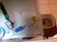
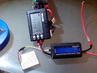
Have made some reasonably hi current discharge test, around 60A. :D
Result:
1)I can push those old Konions 4P to deliver 60A for max. 20 seconds before they fall under 3V/cell.
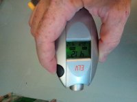
2)No temp raise over ambient on the tabs. Only significant temperature raise is during 1min after every discharge test, cells start heating up from the center of the can and after several consecutive discharge kicks, totaling 1.25Ah (edited) (~1min.15 sec), max temperature registered was 46C at center of the cans.
3)Have 2 digital thermometer, but also only 2 hands, no way to measure temperature in 2 points and take pictures a same time :D
Now some pictures.
IMG_20150204_200514.resized.jpg
The transparent poly prop tape is a place holder for kapton tape. It will react to any thermal event in this testing setup to reveal hot spots.
View attachment 4
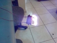
Did the load, but plastic terminals start to melt instantly and I was at risk getting sun burn. :(
IMG_20150204_210514.resized.jpg
Water!! :D
IMG_20150204_210935.resized.jpg
Pack torture. :twisted:
IMG_20150204_211255.resized.jpg
My first idea was to make acrylic boxes around packs, but heat shrink will increase temp exchange eliminating static air over the cells.
IMG_20150204_213535.resized.jpg
 
Now, to the concerning part. Really need help/feedback on this one to proceed!!!
Need to check the fuses in action, but how?

1)I could just sacrifice 1 cell by mechanically shorting it, am prepared to see it heat up and probably melt holder, after the fuses are gone (if they fuse at all), but I am more concerned about possible catastrophic failures like explosions and flaming, have no environment for such events.
2)I could just take 1 cell out and create short in its space.

Other question to anyone with experience in those 18650 internal shorting events. (have disassembled several cells but still do not understand how it works mechanically)
Is it just “pop” and its solid short, or some long going process? (like bleeding cell for a while and short at the end, or slowly lowering resistance or or or)
What is the resistance of internally shorted cell?

Thank you all in advance!
 
Nice to see this. Did you think about bashing it about to see if any sparks or power fluctuation occurred?

Your fuses look quite big to me. Perhaps too big. They do a job often done with skinny balance wires. They don't need to be big fuses. A bit of 3 Amp fuse wire might be adequate. Your cells could pop a 3 amp wire quite quickly while still powering the load. An important consideration. Already loaded cells might not have the power spare to take out your copper strip quickly. Making it a heater.
 
That is simply brilliant idea parabellum :wink:

No need to spotweld.. and you can easy replace cells if needed.

You also added significant protection ( fuse, spacer, insulator..) and that's the way to go sir!

Look like you tought about safety and great current share design. The cells will last longer this way as well!

Last time you bought some Konion pack was in 2011 right?

Even if you buy some more i'll gladly give you a 10% discount

Doc
 
friendly1uk said:
Nice to see this. Did you think about bashing it about to see if any sparks or power fluctuation occurred?

Your fuses look quite big to me. Perhaps too big. They do a job often done with skinny balance wires. They don't need to be big fuses. A bit of 3 Amp fuse wire might be adequate. Your cells could pop a 3 amp wire quite quickly while still powering the load. An important consideration. Already loaded cells might not have the power spare to take out your copper strip quickly. Making it a heater.
Have been thinking about using 36AWG teflon insulated wire for fuses, it is uniform and will take ~3.62A for fusing according to following link and hopefully fail inside teflon with no liquid copper spraying around. Have also 24AWG silicon coated but it is to massive with 29.2A for fusing. Will see if I find something in between, any ideas?
http://www.litz-wire.com/New%20PDFs/Fusing_Currents_Melting_Temperature_Copper_Aluminum_Magnet_Wire_R2.011609.pdf
Even if I start bashing the pack, I have no tools quick enough to measure and record fluctuation and disconnects. We could calculate acceleration of the cell needed to compress one spring to the extend of loosing contact from other side (only missing data is compression strength of spring and other materials in the way). But I believe it will correspond to impacts to concrete wall, at speed where power fluctuation are of less concern.

In any case, describe a test procedure you are interested in and we will see if I have resources to perform it. :)
 
Doctorbass said:
That is simply brilliant idea parabellum :wink:

No need to spotweld.. and you can easy replace cells if needed.

You also added significant protection ( fuse, spacer, insulator..) and that's the way to go sir!

Look like you tought about safety and great current share design. The cells will last longer this way as well!

Last time you bought some Konion pack was in 2011 right?

Even if you buy some more i'll gladly give you a 10% discount

Doc
Yes, about 2011, I am still trying to kill them, with no success. But I am working hard, note the 0.1 written on them. :twisted: But capacity is still there anyway.
Thanks, for the discount proposal! :D
 
parabellum said:
Sorry for the confusion 2.6cm is with contactor pin unbend. With bend or cut off pin LWH 78mmx80mmx21,5mm, but cell is sitting 1,5x mm inside the holder and you can trim it down to 20mm.

Well this is encouraging, I calculated that if the holders are trimmed down to 21.5 mm, I could fit enough of them to go 20S16P of the new US18650VTC5 that Doctorbass is going to sell soon. :p

EDIT:One things about the US18650VTC5. The cells will not be new, they will be the ones in the used BL1850 Makita packs that he should be starting to be getting soon. This year I hope.
 
Had some time on weekend and did a fusing test. As stated in second post, the cell IR does not allow to fuse the whole serie. Shorting 1 cell I got 1 fuse melted in about 2 sec. Next one heated up and melted solder from parallel connection and got opened, third did heating a little without even melting PP tape on top of it.
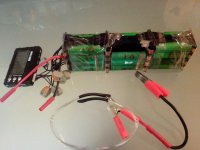
IMG_20150207_210057.resized.jpg
IMG_20150207_212045.resized.jpg
IMG_20150207_212049.resized.jpg
IMG_20150207_212114.resized.jpg
View attachment 2
Other cells are 4,11-4,15V

Conclusion: Even if I take tinny 36AWG fuses and they all melt, the serie string will not be able to melt main 35A fuse and kill 6cells in serial string instead of 4 cells in parallel string.
My series fusing is = Fail.

Fusing every cell will generate significant heat, which is bad without active temperature control.
Unfortunately I will have to live with replacing whole P group in cell internal short event.

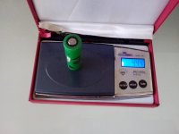
Found my old digital scale and here we have
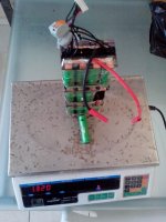
IMG_20150208_133543.resized.jpg
IMG_20150208_133951.resized.jpg
Cell weight 44.4gr for Konions
Pack weight 1320gr
Enclosure weight 254.4gr or 23.9% over cell weight or 19.3% of total weight.
Note:pF, B and BE from Panasonic are heavier and make weight relation better
 
dnmun said:
4.23V is not too much overcharged. not sure why your BMS could not balance it lower but it should pull it down to 4.20V as it sits.
There is no BMS at this experimental stage. All groups where balances before short circuit test to 4.15V/cell, shorting 1 cell holder space caused a parallel connection between 3p2s block and 1p1s cell with virtually 4.15V deference before R, causing high current flow, heating and overcharging.
 
Those metal springs, can they be taken out of the holder and put back in? I'm thinking those springs are made of a continuous piece of metal on either side of the holder, maybe you can fuse that piece of metal between each cell and put the springs back in the holder? I'm hoping I'm making some sense here.
 
mistercrash said:
Those metal springs, can they be taken out of the holder and put back in? I'm thinking those springs are made of a continuous piece of metal on either side of the holder, maybe you can fuse that piece of metal between each cell and put the springs back in the holder? I'm hoping I'm making some sense here.
Yes, they are removable, they are just slide in rail kind holder. Little ditch on springs plain back part is clipping into opening behind to not slide back out. I do not understand what you mean but, fusing the main current path will ad in temperature to already high IR cells, it seems more reasonable just sacrifice the whole 4P string in such a small pack.
Waiting for supplies from HK. Will ad this seller, because transparent heat shrink is way much cheaper, but not PVC, I believe. :(
 
parabellum said:
I do not understand what you mean but, fusing the main current path will ad in temperature to already high IR cells, it seems more reasonable just sacrifice the whole 4P string in such a small pack.

That's just it, I never think of small packs because I don't ride a bicycle, I'm always thinking bigger sized packs, more like 30, 40 or even 50Ah because I ride a scooter, the size of a Vespa 125cc. I don't like the thought of loosing something like a 20P string but I guess that is the consequence of using larger packs made of these 18650 cells.

Have you seen this post from agniusm's thread on his development of a no solder/no weld battery kit.

http://endless-sphere.com/forums/viewtopic.php?f=14&t=63190&start=75#p1006706
 
mistercrash said:
parabellum said:
I do not understand what you mean but, fusing the main current path will ad in temperature to already high IR cells, it seems more reasonable just sacrifice the whole 4P string in such a small pack.

That's just it, I never think of small packs because I don't ride a bicycle, I'm always thinking bigger sized packs, more like 30, 40 or even 50Ah because I ride a scooter, the size of a Vespa 125cc. I don't like the thought of loosing something like a 20P string but I guess that is the consequence of using larger packs made of these 18650 cells.

Have you seen this post from agniusm's thread on his development of a no solder/no weld battery kit.

http://endless-sphere.com/forums/viewtopic.php?f=14&t=63190&start=75#p1006706
Cell level fusing seems to make sense when you can keep using the pack without the cell fused(1or even 2 of) . I have seen the thread and follow all(in my kknowledge) threads of 18650. I still do not understand how it works. :(
 
I'm genuinely impressed! following..
 
Back
Top