Chalo
100 TW
Hey, folding bikes don't really work either, but that doesn't stop some people from riding them. De gustibus non est disputandum.
")
Folken said:Hi guys, I've made an approximate copy of Adrian's bracket and swing arm, and I have a problem: Sometimes, as the drive engages into the tyre, it starts rattling against the stops very hard. It then ends up with bent pin of the swing arm (best case), or the clamp block cracks because of excessive impact force applied to the screw stops. Does anyone know a solution to prevent this rattling?
Blanthegenius said:Hello adrian_sm,
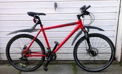
I am looking to build the Commuter Booster system for my mountain bike which I use to commute to work. It's 12 miles round trip.
Searching google led me to this forum. I like what you have done, it looks great and is much cheaper than the alternatives and hopefully for the distance I travel it will work well.
I have a question regarding the "Magic Box".
What would be the less comprehensive alternative/s please?
best regards
Blan
)


windtrader said:Folken,
You listed the controller parts list. What motor and ESC did you use?
windtrader said:Realistically, I guess my vision is more like a serial group buy of standard products, a couple magic components and sufficient instructions and user guide to get some fully rolling and others pretty far. The remaining bit being the adaptation to the specific bike frame. This is all constrained to buyers who "pre-qualify" via actual test fit using the provided template.


 I guess 7 bucks is not a terrible price to pay for peace of mind.