how do you hide/waterproof your controller/ca/motor/lights?

izeman

1 GW
Joined
Jun 21, 2011
Messages
5,131
Location
Vienna, Austria
first of all i have to make a statement: I HATE TO SEE WIRES hanging around or BEING VISIBLE at all.

so based on that statement i did everything to hide the motor and battery wires inside the battery box. the hole box was designed to do that. the motor is encapsulated and the battery and bms as well, so this was easy as no wires went outside the box.

but there still is the CA and 2 led lights to be powered, and the speed signal attached to the CA. as i like to improve/re-install my bike on a regular basis the CA, the throttle, the 3-way switch and the light's supply must be detachable. so i made one single thick wire bundle from the controller to the CA that includes: 6 CA wires (gnd, vcc, sh+, sh-, spd, throttle), 2x led vcc. the throttle and 3-way switch are connected to the CA by a 3-pin JST headers (as pre-installed). and there is this audio-jack hanging from the CA for firmware upgrade.

all this needs to made HIDDEN and WATERPROOF. and i don't know how.

i started to design a box below the CA to home all the connectors, but my 3D-CAD practice makes this a very hard to reach goal.

i could use waterproof connectors. but which ones? they need to be SMALL so i can install them at the controller side covers or on the bottom of the CA.

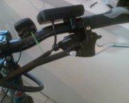
i will make some pictures so you can make yourself a picture what the bike looks like now. this causing my some REAL headaches for several weeks now, and bike season is at my door step ... ;)
 
My messy bit is a multicore to the display, a brake wire, brake pull and gears. Four cables to just one hand.
Brake cable and wire are paired. Display and gear cable are paired. The two pairs are then paired. This turns a normal bikes 2 cables, to my ebikes 4 cables looking like one thick one.
The speedo is just there to calibrate the lcd. It's a build in progress. The throttle side is also sleeved. So I have a single bunch each side, plus the front brake cable. Which my lighting will follow down.
Such tidying is a lot easier with spirawrap than heat shrink. Heat shrink that looks huge here, but it only holds 4 wires. My camera is just a lot closer the wires than the background.
 

Attachments

  • 1PzE6g6X8E.jpg
    1PzE6g6X8E.jpg
    30.2 KB · Views: 3,197
cwah said:
plastic bag?
thanks for your ideas, but sorry. a plastic bag and master of technical engineering don't go together ;) i spent hundreds of hours building my bike, and i'm looking for a professional look and a technically clean solution, not just waterproofing the connections.
 
I don't have connectors in view. My controller is contained. I recently had a controller I could not contain, so chopped the wires off and took the wires from my accessories directly into the box and soldered them in.

I can't wait to take that speedo off. I never fitted it properly as it was never going to look good. I just strapped it on and disowned it. My new speed sensor is on the back wheel, where I had to run a cable along the chain stay I'm really not finished with. No magnet on the spokes though. I stuck one to the motor near the axle and the pickup hides behind my drop-out.

Many commercial bikes are cable tied and spiral wrapped. Sometimes you have to. The only plug I need present is to take my rear wheel off. A plug that is hidden under the wrap that stops the chain hitting the chain stay.


I will wait for the pics to see if I can offer any help specific to your build. I like tidy solutions. At least to oem standards.
 
i guess i will use something like those IP67 connectors, installed at the controller, and a long cable from the CA to the controller.
those connectors are available with up to 9 poles. enough to carry all CA wires and led light supply voltage (contacts are up to 3A), and it's a 13mm hole to install the socket.


taken from: http://www.produktinfo.conrad.com/datenblaetter/725000-749999/734746-da-01-en-KABELSTECKER_9_POL_SP1310___P_9_II.pdf

now i will need to find 3pin waterproof connectors for the throttle and 3way switch.
 
3A for a CA? I guess you have a remote shunt, and the shunt has an op-amp on-board for signal conditioning. Shunts have such a small potential difference across them that using connectors would be a bad idea without some sort of signal conditioning.

Many controllers have space inside for all the connections you could desire. Or you could get the same case and put it end2end as an extension housing, just to stash the wires inside. Bit of paint and nobody will see the join. Your controller box will just get longer. Offering safe harbour for connectors unsuitable for direct exposure.


Just sleeved my front brake cable, to run my lighting wire up from the rim brake area without creating more mess. My lights are going on as an after thought, not in the main build. Bits took to long to arrive. Today the red glass dichroic filter arrived, and now lies as dust on my tiles. Very short lived, but boy was it a tidy item. A mirror to any other colour than red. So the red comes through for my back light, while the blue exits the edge of the glass like angel eyes. Painting things purple. Pics will follow when I buy another :)
 
friendly1uk said:
I guess you have a remote shunt, and the shunt has an op-amp on-board for signal conditioning. Shunts have such a small potential difference across them that using connectors would be a bad idea without some sort of signal conditioning.
The CA uses either the controller shunt or an external shunt. In either case there is no signal conditioning at the shunt end - differential measurement takes care of common mode noise and eliminates ground reference issues. The high impedance pretty much takes connector resistance out of the picture.

By design, the CA routes the {-S,+S} shunt signals through the 6 pin JST CA-DP connector. No problem with another connector at the head unit.
 
oops. posted wrong thread.

edited:

subscribed.
 
izeman said:
i had to learn that there's a reason why the CA wire is 6 poles. and that's it's a bad idea to use the gnd signal instead of -S to save one wire. better use two wires to get a more precise current measurement.
Absolutely.
Also not the best plan to share the CA ground with big current devices like lights. The high current can cause a small ground offset that can affect the throttle or offset thermistor readings if you are powering the thermistor from the motor hall lead.
 
teklektik said:
The high impedance pretty much takes connector resistance out of the picture.

Cheers bud. That didn't cross my mind. Swept along by another forum I must revisit now. Though not the CA in question, but related.
 
Ya - I often have a hard time dancing into design considerations for stuff that's outside my normal purview. Not a question of not understanding - just not getting the proper perspective to ask the right questions. Crap, the world is so big and my brain is so small... :D
 
I put my controller under the seat wires down and the throttle, remote cable operated, in my battery bag. Lots of rain in Portland no troubles yet. Then again it is parked inside, in the living room or in the facilities maintenance shop at werq out of the weather, when not on the road. Camera and lights come off when I arrive and go into my pack if I go somewhere other than home or werq.
 
Izeman, is it a V2 or V3 CA.

V3 is a nightmare to wire with all those leads being so short. I eventually removed them all from the CA and extended them down in to the frame triangle battery box. If you want removable CA though going to need more like 26 pin plug though , not a 9 pin

I suppose throttle, brakes and handle bar switches could be hardwired to the CA, but that is a nightmare too for faultfinding or part replacement.

A bigger case for the CA maybe the answer Dump the original, and build/mould/print / fibreglass yourvown . Buy a new membrane switch for CA Ops, or maybe move CA control to handle bar buttons?. Then you could just run one single multicore PC parallel port size cable down to battery box.

I'd bolt the lights down and make them fixed too, all hardwired to the dc-dc convertor
 
it's a V3. first thing i do when i buy one, is re-wiring it. remove all wires and solder new ones with the correct length.
my first idea was to build something like this to provide some room for the connectors:

case2.JPG
but as i wrote: i'm not really good doing 3D design, so i gave up.

i maybe really will hardwire throttle and 3way as well as lights to the CA's internal. it won't need much space inside. but removing any component will be a nightmare with the CA and throttle, 3way and 2 light dangling below it. :(

but to come back to the needed wires from controller to CA: you need gnd(1), vcc(2), s+(3), s-(4), throttle(5), spd(6), led-(7) and led+(8). what am i missing?
 
Did you not mention 3 amp earlier in relation to the lights?

I'd not run 3 amps through that external CA power connector.

it is only good for 1 amp. it has a thermo resetting fuse set to one amp built on the board.

3. The external DC Power Plug is attached to VF and supplies unregulated +V via a 1A auto-resetting polyfuse.
 
friendly1uk said:
and the shunt has an op-amp on-board for signal conditioning.)


A bit of an aside, but no. the external shunts do not have anything like that .
 
NeilP said:
Did you not mention 3 amp earlier in relation to the lights?
I'd not run 3 amps through that external CA power connector.
it is only good for 1 amp. it has a thermo resetting fuse set to one amp built on the board.
3. The external DC Power Plug is attached to VF and supplies unregulated +V via a 1A auto-resetting polyfuse.
no. i said nothing like that. i said that the connector i found was good for 3A. and the leds are powered by a power supply that is installed inside the battery box. it's wires are routed through the controller (hence led+, led-) to the CA where they are connected to the led lights directly. there is no CA involved. the CA wires and led supply wires just share the same connector.
 
NeilP said:
OK, sorry, thats what comes from reading in the dark on the bloody iPhone!
sorry, i guess it's me trying to be clearer than necessary and that sometimes leads to more confusion ...
i tried to find those 2 or 3pin waterproof plugs with molded wires, but can only find them on alibaba - minimum order 2000 sets :(
http://yychentao.en.alibaba.com/product/296298036-209898845/Waterproof_connector_with_3_pin.html
they look perfect for throttle/3way and for the led's supply.
 
No, its me.
Read it properly and it makes sense.

Connectors are not waterproof, but hestshrink them and use multipin parallel printer plugs/sockets.
Or get down to a boating store
 
Using regen?
If so, you will either want to get a CA Adapter to recover the ebrake signal at the controller, or run an extra wire to carry the signal back to the controller.
I would also recommend an extra wire for a kill switch - you can steal Vbatt from the CA to run the switch (powers the controller 'ignition' connection).
 
Back
Top