fellow
1 kW
[youtube]tc1yCT7UWeE[/youtube]
[youtube]iOmG5BbBXqY[/youtube]
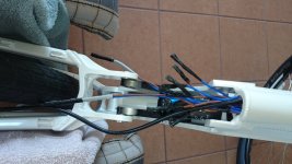
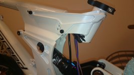
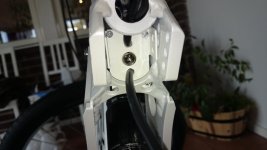
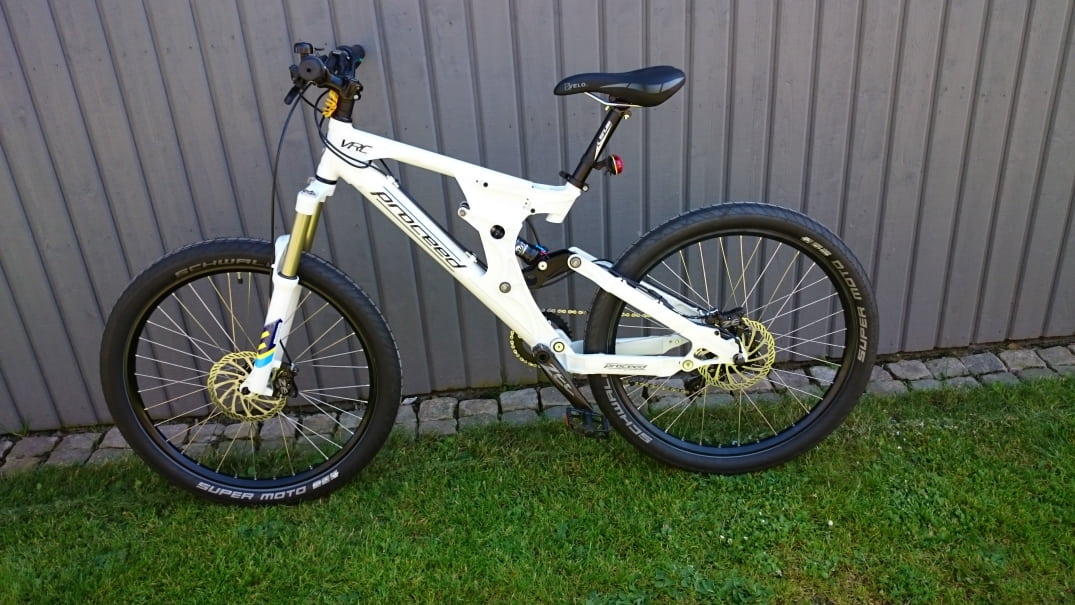
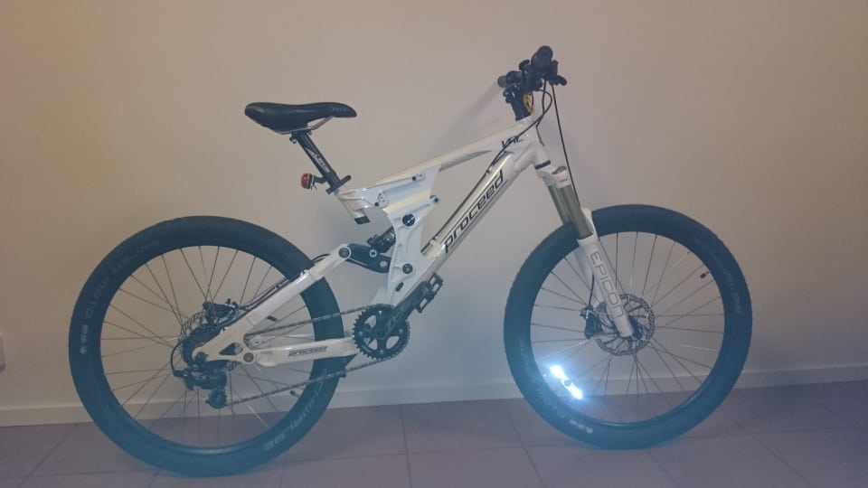
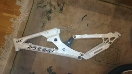
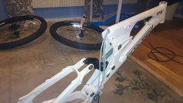
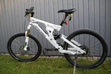
This is the complete ebike with batteries inside the frame tubes, rear hub motor, controller and everything else needed. You have to look really hard to distinguish it from the normal bicycle! The controller is placed above the rear shock absorber with tollerance of less than 2 millimeters.

According to wikipedia, "The Focke-Wulf Triebflügel, or Triebflügeljäger, literally meaning "thrust-wing hunter", was a German concept for an aircraft designed in 1944, during the final phase of World War II. It was a Vertical Take-Off and Landing tailsitter interceptor design. The Triebflügel had only reached wind-tunnel testing when the Allied forces reached the production facilities. No complete prototype was ever built."
Well, now it is")
[youtube]Lb7nX3hblpI[/youtube]
Last movie is screwed up by youtube, "stabilising" it all over the place. As I've already stabilised it in post processing, the end result was not pretty. Lesson learned. Most of the stuf was filmed with a mobile phone, highres pictures with Cannon DLSR, and the end scene with Sony RX100. Will order gopro and try to film in 4k next time.
[youtube]E7hbSgJkpvI[/youtube]
Some pictures of the finished ebike:
Technical data
Tehnical data and the blog below is mostly for my own personal use so I can keep track of the air pressures, oil change dates, oil volumes etc. It is even intended for people that are building their first ebike and need quick and dirty info.
U_charged: 75.6V HOTC (18s2p). 151.2V HOTC possible because of 2 battery 75.6V packs inside. I'm waiting for the To-220 mosfets to evolve, 151.2V is currently not used but is "nice to have" for future use.
I_max: 7A cont, 14A peak. Clutch limited. Thanks to cwah for clutch information and research in this matter.
I_phase: Less than 30A. This is clutch limited too. At 45A, clutch is sometimes making noise (but it climbs like a goat, and do a wheeles with some help). Less range is another drawback. Choosed 30A, 45A is pushing it.
P_in_cont: 0.5kW.
P_in_peak: 1kW. Clutch limited.
Fuselinks: 18A@30seconds silicone insulated 0.75mm2 fuselinks per every 18s pack to protect the NCR18650PF cells in case the damage of the internal wiring. 36A@30 seconds in total in case main fuse fails. Every cell is internally CID/PTC fused.
Main fuse: Littlefuse 0326015.MXP 15A, 125VDC, slow blow. (15A=4h continuous, 20A=1h continuous, 30A=5 to 60 seconds) to protect internal wiring.
Wheels: Schwalbe Super Moto 26"x2.4" or Schwalbe Magic Mary 26"x2.5". Front and rear tyre air pressure is 3 bar. Tubes: Continental 26"x2.5", Dunlop valve.
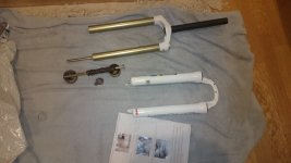
Front suspension: Travel 150mm, air pressure 6 bars. Maximum theoretical frame travel is 200mm+. 50ml of 5W-30 motor oil in the stanchions, 100ml in total.
Rear suspension: Travel 170mm@215mm*54mm shock, air pressure 16 Bars. Rebound set to max anticlockwise. Dampening 0 (open, maximum softness). Maximum theoretical frame travel is 210mm@240mm shock (horizontal top tube).
Brakes: Front 203mm disc, Rear 180mm disc. Shimano Zee hydraulic disc brakes, F+R. 4 pistons per caliper, 8 pistons in total.
Crank: Shimano Zee 36t, Hollowtech II crankset assembly. (1x7 speed hybrid downhill solution)
Derailleur: Shimano Zee RD-M640, short cage, DH.
Freewheel: 7 speed DNP Epoch 11t-32t. This really pushes DH version of the short cage RD-M640 to its limits. Three diamonds 13t-28t freewheel shifted poor, and 36t front-13t rear was simply not enough over 30Km/h. FR version is probably a better choice on other frames. This frame has zero chain grow, so DH version fits.
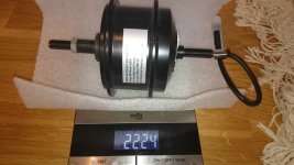
Motor: ATF oil cooled Q100H, 201rpm (223rpm according to Russel/Motomech) at 36V nominal. n_max=(75.6V/36V)*223rpm*15.7=7350rpm at 75.6V, and 14800rpm at 151.2V (Reserved for future use). m=2224g without the freewheel. Internal gear reduction is 15.7:1 (Thanks to Motomech for his research). Maximum oil chamber volume is 80ml, filled at 50% (40ml). When filled at over 50%, motor will develop a heavy leak. Reinforced clutch, se the clutch springs chapter.
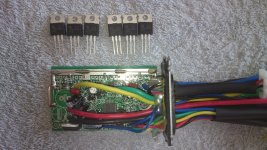
Controller: Frankenstein S06S, third generation (Thanks to Snickers for his research). Mosfets: TI csd19536kcs 100V. Rdsontyp=2_3 mOhm. Maximum recommended DC current is 30A (Q100H 201rpm melting point is at 20A!). Mosfet technobabble: Id_pulsed_drain_current=400A. Id_continuos_drain_current (package limited)=150A.
Alternative mosfet: Infineon IPP023N10N5 100V. Alternative mosfet at 150V voltage is: Infineon IPP110N20N3 G 200V. Rdsontyp=10.7mOhm.
Range first prototype: More than 23km without pedalling, without the external add-on pack at 20'C. Range is less than this at lower temperatures, and more at higher temperatures.
Range second and third prototype: More than 32km without pedalling, without the external add-on pack at 20'C. Range is less than this at lower temperatures, and more at higher temperatures.
Total mass, first prototype: Less than 20Kg. Second and third prototype: Less than 22kg(display added, heavier batteries, Scwhwalbe Magic Mary tires vs Super moto).
Top speed: Limited to 38km/h. More than 50km/h possible (but kills range drastically).
Battery
First prototype: 375Wh (36 Panasonic NCR18650PF cells x 10.4Wh)
Second prototype: 400Wh (36 Panasonic/Sanyo NCR18650GA cells x 11.2Wh)
Ebike charging time: about 3 hours at 2.5A~3A (rapid) bulk charge.
Capacity, voltage and peak current of the first prototype: 5.8 Ah, 75.6V, 36A under 6 seconds peak or 2.9Ah, 151.2V, 18A under 6 seconds peak.
Cells: Panasonic NCR18650PF, total number of cells is 36. Total battery mass 1620 grams + 180 grams wiring = less than 2 KG.
Capacity per cell: Nominal 2.9Ah, IRL 2.7Ah
Max discharge per cell (constant current): 10A
Max discharge pulse current per cell (5-6 sec.): 18A
Full charge per cell: 4.2V
Charging method: CV/CC
Minimum recommended charging current per cell: 0.6A
Rapid charging current per cell: 1.35A and beyond.
Nominal (storage) voltage per cell: 3.6V-3.7V
Minimum recommended discharge voltage level per cell: 2.5V
Target discharge voltage per cell: 2.8V(cell minimum voltage), 3.0V(resting voltage)
Dimensions per cell: 18.5mm x 66.5mm without tabs, 20mm x 70mm with shrink tape, solder and spring formed tabs.
Weight per cell: less than 50 grams
Frankenstein S06S hacking information for V1 2012-2014 and V2 2014-:
 X5=White=Speed Sensor
TS=Green=Throttle signal. Vcc=4.2V. When connected to 5.1V = cutoffs!
RED=+4.2V
TV=Yellow (thick)=Brake signal
Z=Black (my rig) or yellow(thin v2)=Pass
X6=Blue(my rig)=Speed sensor
X4=unknown.
X7=unknown.
XS=unknown. Acts wierd when connected to GND and 4.2V!
LVC=Voltage divider hack
Approx MCU voltages are: LVC if under 3.3V and HVC if over 4.0V. Locate "big" 15kOhm SMD resistor marked 153 and a smaller 1.2kOhm SMD resistor marked 122. Connect your resistor and zener diode of choice in parallel with 1.2kOhm SMD (to the ground, third empty pin hole close to those resistors). Best combination so far is: 3.9V zener diode only, without any resistor. LVC about 64V.
Other less than perfect combinations tested:
15kOhm // 3.9V zener diode. LVC=63.3V /18s=3.5V per cell resting voltage (3.1v/cell sagged). HVC test OK. Cutoffs from standstill at some voltages.
4.3kOhm without zener diode gives LVC 66.5V. Some HVC problems. LVC is tad wrong in my 18S confiq. Range is 20km without pedaling.
6.8kOhm // 4.3V zener diode + 10cm of 0.75mm^2 shunt across ACS712. LVC=64V, but can be drained down to 58.7V. Problems: Phase current to high, sometimes it causes Q100H clutch noise. It stalls at WOT from standstill. That simulation is here: http://www.falstad.com/circuit/circuitjs.html?cct=$+1+0.000005+10.20027730826997+50+5+43%0Ar+288+64+448+64+0+15000%0Av+448+336+448+144+0+0+40+76+0+0+0.5%0Az+288+336+288+176+1+0.805904783+4.3%0Aw+448+336+288+336+0%0As+288+64+288+176+0+0+false%0Ar+112+64+112+336+0+1200%0Ar+48+64+48+336+0+6800%0Aw+112+64+288+64+2%0Aw+48+336+112+336+0%0Aw+112+336+288+336+0%0As+48+64+112+64+0+0+false%0Aw+448+64+448+144+2%0A
30kOhm resistor // 15kOhm + 3.9V zener simulation is here: http://www.falstad.com/circuit/circuitjs.html?cct=$+1+0.000005+10.20027730826997+50+5+43%0Ar+544+176+768+176+0+15000%0Av+768+512+768+256+0+0+40+75+0+0+0.5%0Az+544+512+544+352+1+0.805904783+3.9%0Aw+768+512+544+512+0%0Ar+368+176+368+512+0+1200%0Aw+368+176+544+176+2%0Aw+368+512+544+512+0%0Ar+688+256+544+256+0+30000%0Aw+544+256+544+176+0%0Aw+768+256+768+176+2%0As+688+256+768+256+0+0+false%0As+544+352+544+256+0+0+false%0A
About the simulation: You can double click the voltage source to simulate different battery voltages, and change zener diode voltages, change resistors, disconnect components using switches and so on... I'm unsure if HVC exists, or ACS712 limits the current at very high voltages as it hits the phase current limit (see the phase current hack).
75V hack
To adjust LM317 voltage/current, use 2 x 270 Ohms 3W resistors for 18S NCR18650PF. This puts the resistors at the very edge of what they can take thermally. Tested OK. Better option is to change LM317 to 75V switched voltage regulator Recom R-78HB15-0.5 Another alternatives are:
WRN78U15-500B 3 pin, 15V 18mmx12mmx9mm.
WRN78U24-300B 3 pin, 24V. 18mmx12mmx9mm.
Traco TEN 8-4813 36V-75VDC, 525mA max, 100V 100msec.
Pay attention, pinout for the LM317 and 78xx series is not the same! (Untested, reserved for the future use). Change all high voltage capacitors to 100V. Change mosfets to 100V+ compatible. Add LVC resistor/resistors.
Phase current hack i.e, "snickers hack"
To increase the peak phase current protection limit, a shunt must be added between pins 1 and 4 on ACS712. Possible shunt choices:
10cm of 0.75mm^2 wire shunt increases the phase current from 25A~30A to 38A~45A. Those values are estimatied. Warning! This hack makes Q100H clutch noisy!
5 cm of 0.75mm^2 wire shunt doubles the phase current limit, from 25A~30A to 50A~60A. Those values are estimatied. Reserved for future use (another motor).
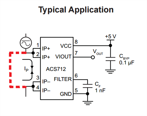
ACS712 pdf is here: http://www.allegromicro.com/~/media/Files/Datasheets/ACS712-Datasheet.ashx
150V hack
Traco TEN 8-7213WI 43V-160VDC voltage regulator instead of LM317. 170V max 100msec. Shutdown voltage 42V. I_max=533mA. Dimensions: 32mmx20mmx15mm. 30USD/piece. Another alternatives are:
WRB11024YMD-3W, 24V, 25mmx25mmx10mm(14mm), 125mA max. 144V(155V) max.
WRB11024YD-3W, 24V, 32mmx20mmx10mm(14mm), 125mAmax. 144V(155V) max.
WRB7215ZD-8W, 15V 32mmx20mmx10mm(14mm), 170V max. 10USD/piece.
LTC7138 max140V!
Pay attention, pinout for the LM317 and 78xx series is not the same! Change all capacitors and mosfets to 200V compatible. Recommended mosfet: Infineon IPP110N20N3 G 200V. Rdsontyp=10.7mOhm. Add LVC diode. Untested, reserved for future use.
Q100H 201rpm@36V clutch springs hack:
Spring holder hole diameter: d=4mm.
Outer diameter of the spring: 4mm<D<3.5mm.
Original spring diameter: 3.85mm
Original spring wire thickness: 0.35mm
Recommended spring wire thickness: As thick as possible. 0.75mm works well.
Spring tension: 1 turn per mm and as strong as possible. Ball pen springs do fit, but you need much stronger ones.
Spring length: 15mm. Cut it as tight (as long) as possible. If you do curse during the install, the length is perfect. If they do not fit, cut them and try again. If it's too easy to install, you probably need a longer spring.
Total number of springs needed: 3
How it's made, see the attachments below.
[youtube]iOmG5BbBXqY[/youtube]
This is the complete ebike with batteries inside the frame tubes, rear hub motor, controller and everything else needed. You have to look really hard to distinguish it from the normal bicycle! The controller is placed above the rear shock absorber with tollerance of less than 2 millimeters.
According to wikipedia, "The Focke-Wulf Triebflügel, or Triebflügeljäger, literally meaning "thrust-wing hunter", was a German concept for an aircraft designed in 1944, during the final phase of World War II. It was a Vertical Take-Off and Landing tailsitter interceptor design. The Triebflügel had only reached wind-tunnel testing when the Allied forces reached the production facilities. No complete prototype was ever built."
Well, now it is
[youtube]Lb7nX3hblpI[/youtube]
Last movie is screwed up by youtube, "stabilising" it all over the place. As I've already stabilised it in post processing, the end result was not pretty. Lesson learned. Most of the stuf was filmed with a mobile phone, highres pictures with Cannon DLSR, and the end scene with Sony RX100. Will order gopro and try to film in 4k next time.
[youtube]E7hbSgJkpvI[/youtube]
Some pictures of the finished ebike:
Technical data
Tehnical data and the blog below is mostly for my own personal use so I can keep track of the air pressures, oil change dates, oil volumes etc. It is even intended for people that are building their first ebike and need quick and dirty info.
U_charged: 75.6V HOTC (18s2p). 151.2V HOTC possible because of 2 battery 75.6V packs inside. I'm waiting for the To-220 mosfets to evolve, 151.2V is currently not used but is "nice to have" for future use.
I_max: 7A cont, 14A peak. Clutch limited. Thanks to cwah for clutch information and research in this matter.
I_phase: Less than 30A. This is clutch limited too. At 45A, clutch is sometimes making noise (but it climbs like a goat, and do a wheeles with some help). Less range is another drawback. Choosed 30A, 45A is pushing it.
P_in_cont: 0.5kW.
P_in_peak: 1kW. Clutch limited.
Fuselinks: 18A@30seconds silicone insulated 0.75mm2 fuselinks per every 18s pack to protect the NCR18650PF cells in case the damage of the internal wiring. 36A@30 seconds in total in case main fuse fails. Every cell is internally CID/PTC fused.
Main fuse: Littlefuse 0326015.MXP 15A, 125VDC, slow blow. (15A=4h continuous, 20A=1h continuous, 30A=5 to 60 seconds) to protect internal wiring.
Wheels: Schwalbe Super Moto 26"x2.4" or Schwalbe Magic Mary 26"x2.5". Front and rear tyre air pressure is 3 bar. Tubes: Continental 26"x2.5", Dunlop valve.
Front suspension: Travel 150mm, air pressure 6 bars. Maximum theoretical frame travel is 200mm+. 50ml of 5W-30 motor oil in the stanchions, 100ml in total.
Rear suspension: Travel 170mm@215mm*54mm shock, air pressure 16 Bars. Rebound set to max anticlockwise. Dampening 0 (open, maximum softness). Maximum theoretical frame travel is 210mm@240mm shock (horizontal top tube).
Brakes: Front 203mm disc, Rear 180mm disc. Shimano Zee hydraulic disc brakes, F+R. 4 pistons per caliper, 8 pistons in total.
Crank: Shimano Zee 36t, Hollowtech II crankset assembly. (1x7 speed hybrid downhill solution)
Derailleur: Shimano Zee RD-M640, short cage, DH.
Freewheel: 7 speed DNP Epoch 11t-32t. This really pushes DH version of the short cage RD-M640 to its limits. Three diamonds 13t-28t freewheel shifted poor, and 36t front-13t rear was simply not enough over 30Km/h. FR version is probably a better choice on other frames. This frame has zero chain grow, so DH version fits.
Motor: ATF oil cooled Q100H, 201rpm (223rpm according to Russel/Motomech) at 36V nominal. n_max=(75.6V/36V)*223rpm*15.7=7350rpm at 75.6V, and 14800rpm at 151.2V (Reserved for future use). m=2224g without the freewheel. Internal gear reduction is 15.7:1 (Thanks to Motomech for his research). Maximum oil chamber volume is 80ml, filled at 50% (40ml). When filled at over 50%, motor will develop a heavy leak. Reinforced clutch, se the clutch springs chapter.
Controller: Frankenstein S06S, third generation (Thanks to Snickers for his research). Mosfets: TI csd19536kcs 100V. Rdsontyp=2_3 mOhm. Maximum recommended DC current is 30A (Q100H 201rpm melting point is at 20A!). Mosfet technobabble: Id_pulsed_drain_current=400A. Id_continuos_drain_current (package limited)=150A.
Alternative mosfet: Infineon IPP023N10N5 100V. Alternative mosfet at 150V voltage is: Infineon IPP110N20N3 G 200V. Rdsontyp=10.7mOhm.
Range first prototype: More than 23km without pedalling, without the external add-on pack at 20'C. Range is less than this at lower temperatures, and more at higher temperatures.
Range second and third prototype: More than 32km without pedalling, without the external add-on pack at 20'C. Range is less than this at lower temperatures, and more at higher temperatures.
Total mass, first prototype: Less than 20Kg. Second and third prototype: Less than 22kg(display added, heavier batteries, Scwhwalbe Magic Mary tires vs Super moto).
Top speed: Limited to 38km/h. More than 50km/h possible (but kills range drastically).
Battery
First prototype: 375Wh (36 Panasonic NCR18650PF cells x 10.4Wh)
Second prototype: 400Wh (36 Panasonic/Sanyo NCR18650GA cells x 11.2Wh)
Ebike charging time: about 3 hours at 2.5A~3A (rapid) bulk charge.
Capacity, voltage and peak current of the first prototype: 5.8 Ah, 75.6V, 36A under 6 seconds peak or 2.9Ah, 151.2V, 18A under 6 seconds peak.
Cells: Panasonic NCR18650PF, total number of cells is 36. Total battery mass 1620 grams + 180 grams wiring = less than 2 KG.
Capacity per cell: Nominal 2.9Ah, IRL 2.7Ah
Max discharge per cell (constant current): 10A
Max discharge pulse current per cell (5-6 sec.): 18A
Full charge per cell: 4.2V
Charging method: CV/CC
Minimum recommended charging current per cell: 0.6A
Rapid charging current per cell: 1.35A and beyond.
Nominal (storage) voltage per cell: 3.6V-3.7V
Minimum recommended discharge voltage level per cell: 2.5V
Target discharge voltage per cell: 2.8V(cell minimum voltage), 3.0V(resting voltage)
Dimensions per cell: 18.5mm x 66.5mm without tabs, 20mm x 70mm with shrink tape, solder and spring formed tabs.
Weight per cell: less than 50 grams
Frankenstein S06S hacking information for V1 2012-2014 and V2 2014-:
X5=White=Speed SensorTS=Green=Throttle signal. Vcc=4.2V. When connected to 5.1V = cutoffs!
RED=+4.2V
TV=Yellow (thick)=Brake signal
Z=Black (my rig) or yellow(thin v2)=Pass
X6=Blue(my rig)=Speed sensor
X4=unknown.
X7=unknown.
XS=unknown. Acts wierd when connected to GND and 4.2V!
LVC=Voltage divider hack
Approx MCU voltages are: LVC if under 3.3V and HVC if over 4.0V. Locate "big" 15kOhm SMD resistor marked 153 and a smaller 1.2kOhm SMD resistor marked 122. Connect your resistor and zener diode of choice in parallel with 1.2kOhm SMD (to the ground, third empty pin hole close to those resistors). Best combination so far is: 3.9V zener diode only, without any resistor. LVC about 64V.
Other less than perfect combinations tested:
15kOhm // 3.9V zener diode. LVC=63.3V /18s=3.5V per cell resting voltage (3.1v/cell sagged). HVC test OK. Cutoffs from standstill at some voltages.
4.3kOhm without zener diode gives LVC 66.5V. Some HVC problems. LVC is tad wrong in my 18S confiq. Range is 20km without pedaling.
6.8kOhm // 4.3V zener diode + 10cm of 0.75mm^2 shunt across ACS712. LVC=64V, but can be drained down to 58.7V. Problems: Phase current to high, sometimes it causes Q100H clutch noise. It stalls at WOT from standstill. That simulation is here: http://www.falstad.com/circuit/circuitjs.html?cct=$+1+0.000005+10.20027730826997+50+5+43%0Ar+288+64+448+64+0+15000%0Av+448+336+448+144+0+0+40+76+0+0+0.5%0Az+288+336+288+176+1+0.805904783+4.3%0Aw+448+336+288+336+0%0As+288+64+288+176+0+0+false%0Ar+112+64+112+336+0+1200%0Ar+48+64+48+336+0+6800%0Aw+112+64+288+64+2%0Aw+48+336+112+336+0%0Aw+112+336+288+336+0%0As+48+64+112+64+0+0+false%0Aw+448+64+448+144+2%0A
30kOhm resistor // 15kOhm + 3.9V zener simulation is here: http://www.falstad.com/circuit/circuitjs.html?cct=$+1+0.000005+10.20027730826997+50+5+43%0Ar+544+176+768+176+0+15000%0Av+768+512+768+256+0+0+40+75+0+0+0.5%0Az+544+512+544+352+1+0.805904783+3.9%0Aw+768+512+544+512+0%0Ar+368+176+368+512+0+1200%0Aw+368+176+544+176+2%0Aw+368+512+544+512+0%0Ar+688+256+544+256+0+30000%0Aw+544+256+544+176+0%0Aw+768+256+768+176+2%0As+688+256+768+256+0+0+false%0As+544+352+544+256+0+0+false%0A
About the simulation: You can double click the voltage source to simulate different battery voltages, and change zener diode voltages, change resistors, disconnect components using switches and so on... I'm unsure if HVC exists, or ACS712 limits the current at very high voltages as it hits the phase current limit (see the phase current hack).
75V hack
To adjust LM317 voltage/current, use 2 x 270 Ohms 3W resistors for 18S NCR18650PF. This puts the resistors at the very edge of what they can take thermally. Tested OK. Better option is to change LM317 to 75V switched voltage regulator Recom R-78HB15-0.5 Another alternatives are:
WRN78U15-500B 3 pin, 15V 18mmx12mmx9mm.
WRN78U24-300B 3 pin, 24V. 18mmx12mmx9mm.
Traco TEN 8-4813 36V-75VDC, 525mA max, 100V 100msec.
Pay attention, pinout for the LM317 and 78xx series is not the same! (Untested, reserved for the future use). Change all high voltage capacitors to 100V. Change mosfets to 100V+ compatible. Add LVC resistor/resistors.
Phase current hack i.e, "snickers hack"
To increase the peak phase current protection limit, a shunt must be added between pins 1 and 4 on ACS712. Possible shunt choices:
10cm of 0.75mm^2 wire shunt increases the phase current from 25A~30A to 38A~45A. Those values are estimatied. Warning! This hack makes Q100H clutch noisy!
5 cm of 0.75mm^2 wire shunt doubles the phase current limit, from 25A~30A to 50A~60A. Those values are estimatied. Reserved for future use (another motor).
ACS712 pdf is here: http://www.allegromicro.com/~/media/Files/Datasheets/ACS712-Datasheet.ashx
150V hack
Traco TEN 8-7213WI 43V-160VDC voltage regulator instead of LM317. 170V max 100msec. Shutdown voltage 42V. I_max=533mA. Dimensions: 32mmx20mmx15mm. 30USD/piece. Another alternatives are:
WRB11024YMD-3W, 24V, 25mmx25mmx10mm(14mm), 125mA max. 144V(155V) max.
WRB11024YD-3W, 24V, 32mmx20mmx10mm(14mm), 125mAmax. 144V(155V) max.
WRB7215ZD-8W, 15V 32mmx20mmx10mm(14mm), 170V max. 10USD/piece.
LTC7138 max140V!
Pay attention, pinout for the LM317 and 78xx series is not the same! Change all capacitors and mosfets to 200V compatible. Recommended mosfet: Infineon IPP110N20N3 G 200V. Rdsontyp=10.7mOhm. Add LVC diode. Untested, reserved for future use.
Q100H 201rpm@36V clutch springs hack:
Spring holder hole diameter: d=4mm.
Outer diameter of the spring: 4mm<D<3.5mm.
Original spring diameter: 3.85mm
Original spring wire thickness: 0.35mm
Recommended spring wire thickness: As thick as possible. 0.75mm works well.
Spring tension: 1 turn per mm and as strong as possible. Ball pen springs do fit, but you need much stronger ones.
Spring length: 15mm. Cut it as tight (as long) as possible. If you do curse during the install, the length is perfect. If they do not fit, cut them and try again. If it's too easy to install, you probably need a longer spring.
Total number of springs needed: 3
How it's made, see the attachments below.
Attachments
-
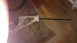
 Picture nr 1 - Proceed Epicon side shot.JPG54.5 KB · Views: 18,201
 -
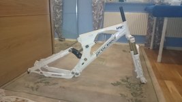
 Picture nr 2 - Increasing the travel to 150mm.JPG52 KB · Views: 18,201
 -
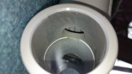
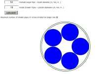 Picture nr 3 - 52mm outside and 19mm inside.jpg33 KB · Views: 18,202
 -
 Picture nr 4 - Battery inserting.JPG43.1 KB · Views: 18,201
 -
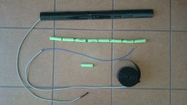
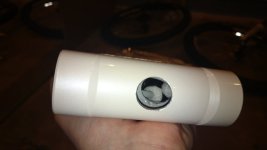 Picture nr 5 - What's inside.JPG26.3 KB · Views: 8,509
 -
 Picture nr 6 - Batteries inside.JPG58.4 KB · Views: 18,201
 -
 Picture nr 7 - 24s 100.8V, 8s left to go.JPG61.8 KB · Views: 18,201
 -
 Picture nr 8 - Let's make some more batteries, there is sitll place! DSC_0071.JPG59.8 KB · Views: 18,192
 -
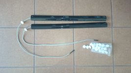 Picture nr 9 - The white stuff is to absorb big hits as this is downhill e-bike. I'm using 4 o...JPG55 KB · Views: 18,190
 -
 Picture nr 10 Wiring inside head tube.JPG42.6 KB · Views: 8,504
 -
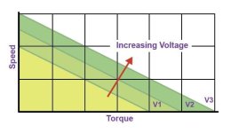 Picture nr 11 BLDC_IncreasingVoltage.jpg17.4 KB · Views: 17,855
 -
 Picture nr 28.JPG39.7 KB · Views: 8,496
 -
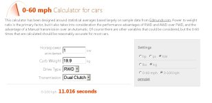 0-100 Triefluegel.jpg44.7 KB · Views: 8,494
 -
 IMG_3401 ok resides.JPG124.2 KB · Views: 15,684