Compact Field Oriented Controller, ASI + Grin, limited run

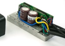
On the left is the CNC'd enclosure for the BAC500+ devices that we made in a limited one-time run last year and which this thread was all about. On the right is the BAC800 circuitboards (72V capable) along with the the heatsink and wiring harness that we made, and in the middle is the expected geometry of the finished Grin modified BAC800 device once it is potted. So shorter and narrower but also taller than the CNC'd enclosures. More power in less volume overall
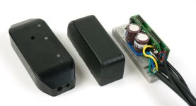
BAC800 Prototype Compared.jpg

Question for you guys. Do you prefer having all the cables coming out of the same one end of the controller, or do you prefer when there is a logical flow through of the power, with the battery leads coming in from one end and then the controller leads going out the other end? I'm usually partial to the flow-through concept, but in this one case the manufacturing for us will be a lot easier if the cables all come out the back as depicted. I'm curious if others have strong opinions about this, and if it would be worth us making a more complicated mold that has cable exits from both ends.
 
Now THAT is a beautiful little controller :)

I also prefer to have all leads on one end. Maybe you can show us an example of clean feed-through wiring, and maybe you can sway us the other direction :mrgreen:
 
riba2233 said:
I prefer everything on the same end.

OK, that seems pretty definitive from this small groups at least. Will proceed for now with all cables on one end then!

Where are the fets?

They are sandwitched between the aluminum heat sink on the bottom and an aluminum spreader on the top. This way we have direct metal contact on all exposed metal of the TO-220 package, rather than just on the back face. You can see the 6 fets more clearly in this shot, the top spreader plate has 6 threaded holes in it and the screws go in from below:
BAC800 Unpotted Closer View.jpg

We've just finished CNC machining a half dozen of these heatsink pieces and have sent them out for engineering hardcoat anodizing so that they are electrically isolating and can be installed without any insulating pad. Give them a week to get back here and we can start finalizing these prototypes.
 
justin_le said:
Do you prefer having all the cables coming out of the same one end of the controller, or do you prefer when there is a logical flow through of the power, with the battery leads coming in from one end and then the controller leads going out the other end?
It would depend on where everything is on the vehicle.

If a battery is at one end of the vehicle, motor at the other, and controller between, it would make sense to have cables in flow-thru layout.

If a battery and motor are at the same end with controller somewhere right there, it would not much matter in most cases, and same-end exit might be useful for mounting options.


If all cables come out one end it does make it easier to mount it in "pockets" in the frame without worrying about curving wires back around it to route them back to various stuff.
 
the compact size is aweseom. great job.
what will be the rated (continuos) power?
as for the wire exits it depends on the application and bike etc, but for waterproofing it would be better to have them all on one side..
 
justin_le said:
riba2233 said:
I prefer everything on the same end.
OK, that seems pretty definitive from this small groups at least. Will proceed for now with all cables on one end then!

+1 for cables all all on one end. Besides allowing for cleaner looking installs, it's handy to be able to orient the controller such that water will flow away from the cables exits instead of flowing along the cable and into the controller.

The Grin+ASI controller is well sealed but it never hurts to play it safe with water ingress.
 
Would it be better if the base of the controller was mounted upside down so that the FET side has more airflow? Maybe even a finned case for extra cooling so that we can push it further. :twisted:
 
So this controller will be programmeable ?

will we be able to program field weakening for higher top speed ?
 
Fully! :D you need to read the thread from the first post!
 
I like the anodised heatsinks on both sides of the fet. But i wounder how will you keep the screw from conducting to the mosfet housing ? its very easy for the screw thread to break through the anodiseing hence the screw will be alive and hence if it touches the inside of the fet hole it will conduct. Normal to220 bushes won't fit unless their is room above the fet?
 
Gab said:
I like the anodised heatsinks on both sides of the fet. But i wounder how will you keep the screw from conducting to the mosfet housing ? its very easy for the screw thread to break through the anodiseing hence the screw will be alive and hence if it touches the inside of the fet hole it will conduct. Normal to220 bushes won't fit unless their is room above the fet?

It does not look like there is any insulation under them going by the photo. Would prefer from a mechanical stand point to have screws going in the opposite direction so you would have some longer thread engagement if it is possible to get at them easy enough for repair issues. Looks like it is already set to get threaded holes in the base, so it would not change machine setup.
 
speedmd said:
Gab said:
I like the anodised heatsinks on both sides of the fet. But i wounder how will you keep the screw from conducting to the mosfet housing ? its very easy for the screw thread to break through the anodiseing hence the screw will be alive and hence if it touches the inside of the fet hole it will conduct. Normal to220 bushes won't fit unless their is room above the fet?

It does not look like there is any insulation under them going by the photo. Would prefer from a mechanical stand point to have screws going in the opposite direction so you would have some longer thread engagement if it is possible to get at them easy enough for repair issues. Looks like it is already set to get threaded holes in the base, so it would not change machine setup.


The aluminum will be hard-coat anodized (not shown in the pictures), meaning the FETs will be electrically isolated from the heatsink bodies. We'll apply some thermal paste between the FETs and the heatsinks. The screws themselves will also be isolated from the larger heatsink as well as the FETs by use of shoulder washers from the backside of the larger heatsink. Due to the nature of the threading and hard-coat anodizing, the screws will be linked electrically to the heatspreader - but this is okay. The screws will only need to be torqued (and have a thread locking compound applied) once as they won't be a serviceable part (entire controller is potted in epoxy). We may not even have them accessible in the final part (tbd).

Hopefully, we'll be getting the hardcoated prototypes back this week and then we can start testing the potting and thermal performance of the heatsinks as currently designed! Woo! I'm excited about these little guys, they show a lot of promise!

*edit: spelling
 
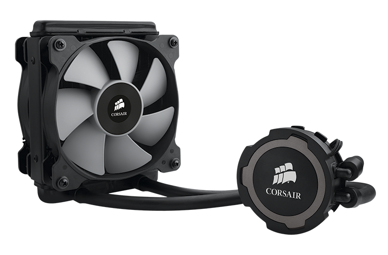
How about making bottom plate a bit thicker (if its not thick enough) to drill out couple 6mm holes (for DIY modders) for water loop, say something like this:
T1ugIQFbhXXXXXXXXX_!!2-item_pic.png

No doubt there will be people pushing these babies :D
 
agniusm said:
How about making bottom plate a bit thicker (if its not thick enough) to drill out couple 6mm holes (for DIY modders) for water loop, say something like this:
T1ugIQFbhXXXXXXXXX_!!2-item_pic.png

No doubt there will be people pushing these babies :D


It appears you could bolt the lower section to a water block if needed. No need to make every unit have the extra weight for the few who want to liquid cool.
 
Forgive me if I missed it because I did try to read the entire thread... but is this REALLY silent on RC motors too?

Because this new block style (with the wires coming out the same side :mrgreen: ) BAC800 combined with a kepler style friction drive would make an ideal commuter-helper for my bike.

But I am really curious if a cheap RC motor like a Turnigy SK3 will be silent with this controller, since they're normally so whiny. I see the hub motors are silent, and thats a great sign, but...
 
liveforphysics said:
It appears you could bolt the lower section to a water block if needed. No need to make every unit have the extra weight for the few who want to liquid cool.

It looks to me that the bottom plate is something like 6-7mm. Adding a 1-2mm and milling out 2 5-6mm holes right through will add little to no weight and moding it for water cooling will be accessible even for noobs with off the shelf parts. I dont think it would add significant cost to manufacture. Just my 2 kopeika :)

P.S. or that:

speedmd said:
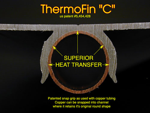
When the numbers can justify a custom extrusion, the base can have cooling fins designed in that would work well both for air or water.
2TFinCopperFit.jpg
 
Back
Top