Suzuki RF400E, now with Enertrac MHM602

Long time no posting, sorry guys.
Took her for a spin last night - first time actually after upping the programmed power settings to about 6kW and half a charge (see below):

Not too happy, though - accelleration in first gear is nice, getting peaks of about 5.5kW but quickly tapering off as the rev limit is reached (~35km/h in 1st), 2nd trying to pull the same power usually leads to controller shutdown (back on throttle release)...

In the meantime I worked on soldering the 24s Zephyr and wrestled with my Menwell USP-500s. Lesson to be had here: Do not use power supplies to charge a battery pack without additional current limiter :pancake: (like Fechter's board - many thanks for that BTW, built it on perfboard).
2nd replacement PSU is on the way...

Also finished mounting the IKEA hinge for the now fake tank cover:

Minor mods on the plate where the thermostat etc. were mounted:

(in the meantime the wood has been replaced with a larger PE plate, IKEA Legitim FTW :))

@parabellum:
some pics from the drivetrain after my first commute. Probably oversped the motor by downshifting, but some Loctite won't hurt on the little bolts on the Alien can either. Replaced with the Turnigy's can (where this wasn't an issue, even with 90V@kV130) for now, added two 12V fans, too, for good measure.
The belt pulley is entirely my fault - too much pressure on the rim when taking it off repeatedly during all the testing. How it ended up THAT mangled is a mystery, though. Still able to use the pulley on the 2nd motor, once I get to that.


(Note: white cable is from a cheap fridge type digital thermometer.)
 
parabellum said:
Thanks! Nice work. Hope, you get it working. Would be interesting to see efficiency numbers.
P.S. What is the difference between Alien and Turnigy?(except halls)

Not much:
Alien has better finish and bearings, slightly different can design.
Major advantages are:
- it's still available :)
- Bruno has them in a number of kV options (I have the kV=80 in WYE)
- halls are an option with the 10mm longer versions, they have a PCB for them, but out of stock - I just added mine the same way, epoxied into the slots
 
OK, I'm making some progress:

  • - I got the two (now new) USP500s to current limit with a breadborded "Version 3 Mini Meanwell Limiter" clone (many thanks for posting the design, Fechter!)
  • - charged nicely to 91.5V (for now) without popping a breaker, very satisfying 8)
  • - with that I could resume test drives, suddenly hitting massive cutouts on even medium acceleration...
  • - programmed the little 12FET to think it is a 18FET, 100A battery & 175A phase
    now you need to remember that it thinks it has three shunts, but actually still has two so we're scaling down by 1/3
    this nets 66A battery and 117A phase, CA shows peaks of 8-9kW
  • - this made medium accelleration reliable but on the occasional "reflex" WOT in traffic (bike is taxed and insured, thanks MCE!) the cutting out makes it too dodgy to use
  • - put a 1kΩ resistor across C20 as per http://endless-sphere.com/forums/viewtopic.php?f=2&t=16910&start=50#p253838 - that finally did the trick :wink:
  • - test drive went OK, but after 1km uphill the bike died, CA showing 10240W
    I thought I pushed the controller too hard and blew some FETs, so pushed the bike home
  • - tested the controller's resistances (=/- vs phases) and didn't find a fault...
  • - opened the controller and found the yellow CA connector cable (shunt+) disconnected - see http://www.ebikeschool.com/add-cycle-analyst-connector-controller/ for details
    that meant obviously the CA thought I had an overcurrent situation and "grounded" the throttle input
    in retrospect the 1024 (2^10) scaled by a factor of 10 do make a different sense now...
  • - soldered it back onto the shunt, took her for a spin in the neighborhood, only to have the same failure occur again, controller still working with the CA unplugged

I'm a little worried about heat now inside the controller (outside maybe 50°C at the FET mounting), as the soldering joint is solid here on the table at room temperature.
Any comments?

On a related note, the Zephyr side-project is nearly done, too. It will have some unique packaging :D.

Some pics:

(sorry for the quality, phone doesn't like macro and the wife has the good camera to stalk the offspring these days :))

BTW, I'll fix and publish the Fritzing schematics for the breadboarded Limiter clone (schematic pinout is different from Fechter's, that was some fun) if there's interest. I will check with him first, though, as it's his design.
 
:D ,, why do the bottom motor stop quicker than the top ? .. im guessing the vid is without any thing connected to the motors.. they should stop at the same time are you driving each motor from identical pair of controllers ?.
 
The bottom one had no pulley on the drive belt, which might have been in the way of the top one, too.
But it's a good thing to look out for - I'll check them under the same condition - gearbox is out atm to fix the oil leaking into the "overflow".
 
did you get to the bottom of the cutting out ?

also make sure that the kv are the same on both motors as this can also cause problems they dont have to be exact but ideally the nearer the better .. I know you have your halls mounted in the slots so tweeking the timing is not a option but this may be the problem with the cutting out.
 
gwhy! said:
did you get to the bottom of the cutting out ?

also make sure that the kv are the same on both motors as this can also cause problems they dont have to be exact but ideally the nearer the better .. I know you have your halls mounted in the slots so tweeking the timing is not a option but this may be the problem with the cutting out.

Cutting out was due to overcurrent lockout - C20 bridged with 1kΩ did the trick AFAICTSF.
They are both 7 turn WYE.
 
ok so in theory they should be the same kv.. I have never had any of my 80mm outrunners tripping a 12fet nor a 6 fet for that matter.. My sensors are external and can be tuned to elimiate the hardwired trip.. I think as you have wye terminated motors and if you have the sensors in the slots this my be a problem that will cause excessive high phase currents .. but I hope it will all be fine and Im wrong.
 
gwhy! said:
ok so in theory they should be the same kv.. I have never had any of my 80mm outrunners tripping a 12fet nor a 6 fet for that matter.. My sensors are external and can be tuned to elimiate the hardwired trip.. I think as you have wye terminated motors and if you have the sensors in the slots this my be a problem that will cause excessive high phase currents .. but I hope it will all be fine and Im wrong.


Did you run 96V, too? I=V/R
 
Ok, did some tidying up with PP plates (IKEA cutting board, love to work with that material), fixed brakes and mirrors(broke off), did some chain maintenance and I think she's ready for a dual motor test ride :) in the next few days.
The only thing missing for daily use are the fans to cool the motors. Possibly the fairings...
Anyway, some pics in the meantime:

I just love how much space there is under the "hood" 8)
 
Well I noticed a imbalance in the motor heat and pulled the top controller which needed a "nudge" in one out of three attempts, here's why:
SDC17953_zpsogrttyzv.jpg
 
After a long absence I'm reviving this thread.
Forays into the Lebowski controller sub-scene :) 
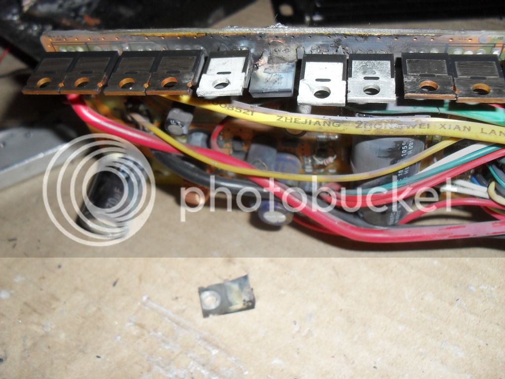
& trying a Powervelocity 18FET proved fruitless so far, so I'm turning this around:
I scored kind of a "kit" in Europe, notably with an Enertrac MHM602 & a KHB14301:

As this came from Ardjan's GSX750, the shaft of the RF400 doesn't fit, it's 20mm diameter vs 17.5 of the GSX750 (or as supplied by Enertrac, don't know really). Length of the smooth part has to be 310mm (or 320 with washers).
I've requests out with two MB breakers, but if anybody knows a bike that precisely has this shaft, let me know.
Once I can position it in the bike I can order distance holders and some aluminium stock to fabricate the spacers and the torque arm's mount.
 
Apparently no bike has this kind of axle, checked on the RF900: though the box sections of the swingarm are 10mm wider each, Suzuki decided to have them taper off towards the rear, making the axle the same as on the RF400, 20mm by 310mm plus thread and head.
I ordered one to be made from a local machine shop now.

Also compared the wheel weights:
- original RF400 wheel with tyre, 525 sprocket & chain, brake disk and caliper: ~20.5kg
- Enertrac MHM602 with spoked 2.15x17 rim & 130/90H tyre fitted, torque arm and caliper: ~35kg


Modified gearbox is ~21kg plus the 2x 80100s, clutch lever assembly & oil say another 5-6kg means I'm ahead 10-12kg, not bad :mrgreen:
I fitted a plate to hold the bottom 4 modules up but it looks like I need some more bracing, probably a bracket or two made from a bent pipe, we'll see.
 
Nice to know its still going, shame you never got the Lebowski boards and 80/100 going perfect. Soon enough Bobc and I might have a real highway capable Lebowski on the go but that's all really in his hands. In principle we have this working sensored and sensorless with a 4kw hub motor. So hopefully this will be the year the scooters get faster and smoother. Good luck with the new direction. :D
 
Cheers, the opportunity hopefully proves to be a "boost" to the project.
I put the axle in last weekend (took 2.5h of careful filing the Enertrac's aluminium center until it went through, maybe .25mm, didn't realize it tapered a bit at the ends).
It's a snug fit now, I made my measurements and ordered some stock from Forward Metals - they are brilliant for "just a few small pieces" :)
We all deserve a picture now:

(yes, I'll fix the rust once she's on the road - any suggestions for colours?)

Wiring harness for the Kelly is next.
 
Some more progress:

- built the cable for the Kelly J2 connector
- the Forward Metals' stuff arrived, already drilled the worst one a bit (44mm long, 6 out of 17.5mm ID so far)

 
Slow but steady progress on the metal work.
Worst part was the spacers (drilling 17.5mm hole with handheld tools and drills only up to 10mm...).
The square block to slot in precisely :eek: into the brake holder mount on the swingarm was a close second. I also ground off the heads of the first two bolts to hold it to the torque arm/brake mount - they'd foul the brake disk otherwise.
The last two pieces will just form a clamp - two cutouts, six holes and four threads.

Have a look and tell me it's over-engineered :shock: :D
 
I made good progress on the mechanical side, aluminium parts for the rear wheel are all done and fitted:

As you can see in the next picture, the fit is so tight that you can actually put the wheel in the swingarm without it falling out:

 
First test ride with MHM602:[youtube]WLO0p4OO4A8[/youtube].
I went through the 36 combinations afterwards and found a slightly better one.
There are some problems with the setup, the Kelly conks out at more than about half throttle.
 
Back
Top