r3volved
100 kW
Did you try another throttle?
teklektik said:Please explain: 'worked intermittently' -- Throttle goes on and off during the same power-up state, throttle does not work at all occasionally after power-ups, etc?
What type of battery do you actually have and what battery setting did you set your CA?ebike11 said:Hi guys
My Ah reading seems to be way off.
Is this because of the Battery type or other settings that I could have incorrectly entered during set up? Thx
r3volved said:What type of battery do you actually have and what battery setting did you set your CA?ebike11 said:Hi guys
My Ah reading seems to be way off.
Is this because of the Battery type or other settings that I could have incorrectly entered during set up? Thx
If you setup the wrong chemistry it would be off.
No. Ah reading is independent of the chemistry and Ah configuration which are used for the Gas Gauge feature.ebike11 said:My Ah reading seems to be way off.
Is this because of the Battery type or other settings that I could have incorrectly entered during set up?


flashes if there the input voltage exceeds the configured value of ThrI->FaultVolt, indicatinga throttle fault voltage – typically caused by a broken throttle Gnd connection,
A new feature was added subsequent to 3.0p6 that blocks Throttle Output if Throttle Input is not ZEROed on power-up. This error state is cleared once the throttle goes to the configured ZERO voltage - allowing normal Throttle Out operation. This was the cause of my request above for details of the circumstances of your intermittent failures (the Guide is not up to the present 3.0p9 firmware and does not call out this behavior and failure indication).teslanv said:Then this morning the throttle slider was flashing, and the bike was NOT working.
Guide said:flashes if there the input voltage exceeds the configured value of ThrI->FaultVolt, indicating a throttle fault voltage – typically caused by a broken throttle Gnd connection,
Excellent news!teslanv said:I think you nailed it there. I think I set the Thrl->MinInput to the Actual Throttle Input Voltage of 08.3V :?
Will change to 1.03V and see if that solves it.
You asked this same question on the previous page.BoomerChomsi said:I would like to use regenerative braking, too bad my controller need 12V to work.
....
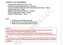
teklektik said:It is unclear from your description what your controller expects for input (12V or Gnd to assert brakes?).
Please identify which controller you are using and supply a PDF or link to the documentation so we can understand the actual electrical requirements of your controller ebrake input.

No - Pin 1 is the sense input and must be configured using the software to be ebrake (regen) -- see section 4.4 of manual.BoomerChomsi said:So switching pin 11 to pin 1 will activate e-brake?
Pin 1 is like ground?
izeman said:a short question about "battery internal resistance": how often is this display refreshed? i know how it's calculated (max voltage sag/max current), but it seems to be nailed to a value which doesn't change even a bit, even a thousand of a ohm.