10S custom skate ESC: testers wanted!

silviasol said:
Are you certain that the positive and negative connections were not crossed when you plugged it in? I had one board I did that by accident and when I plugged in the programmer it was flashing lights strangely so I knew something was wrong. I found even though the wiring looked fine the power leads were crossed. I think the wiring was just barely touching the d4 contact next to the positive connection. I fixed the wiring then next time I plugged it in the d5 and u2 chips would get hot and start smoking. I always double check the positive connection with a multimeter now, the last board I did also had a crossed connection which I luckily caught before plugging it in.

Hey Silviasol I am about 98% certain that I never connected it incorrectly.
The main fault that burned my drv8032 was a voltage peak from a missing electrolytic capacitor on the input.
Now after replacing it it still only works partially and I am trying to figure out if either the new drv is damaged or if any other components got killed by the sudden peak.
 
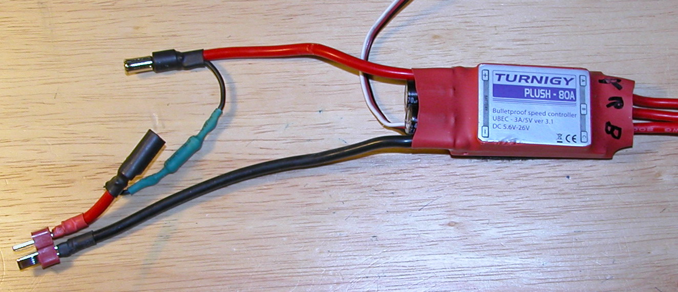
Would a wiring setup like this work to stop the spark? I have an vesc here that the spark was so bad it actually ate away at the positive metal.

a5195330-41-DSCN0002.jpg
 
Hi guys Iv gotten the video logger semi working on windows and OS X.
We will pop this on line soon!

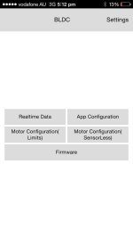
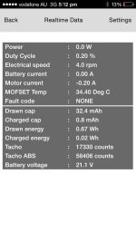
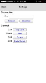
Also have been working on a iOS and android all, we are keeping the look basic ATM but will fix this soon!
Take a look at some screen shots!

image.jpg

image.jpg

image.jpg

Let me know of things if you think they need to be changed!
 
Just finished soldering my VESC, connected battery, checked all voltages-everything looks ok, but DRV8302 is getting hot even when nothing is connected to the ESC. What might be the problem, any ideas?
Inspected the board several times with microscope. everything looks ok...
 
jeffpetersen said:
Just finished soldering my VESC, connected battery, checked all voltages-everything looks ok, but DRV8302 is getting hot even when nothing is connected to the ESC. What might be the problem, any ideas?
Inspected the board several times with microscope. everything looks ok...

Check the pins that they are not loose and unconnected with the board. I use a pin along with the microscope, if they are loose you will see them move by applying a bit of pressure to each pin.
 
Heated up the IC with hot air again, things got better. It is still warm (as it supposed to be), but stable. I think the GND pad was not soldered properly...
 
silviasol said:
Would a wiring setup like this work to stop the spark? I have an vesc here that the spark was so bad it actually ate away at the positive metal.

a5195330-41-DSCN0002.jpg

This seems like the best anti spark option.

uCmkh6yqDwgK8yGP48sT_AMLLfT_TQbBPlssddAqrmXKlHarXe9q4Wz_uH-614vjLhuM2Homi8XjvO3YegAgT0NHHmriTto0iVk9Z2jNwiUpKkt6WqJ0UvR0=w386-h381-nc
 
onloop said:
silviasol said:
Would a wiring setup like this work to stop the spark? I have an vesc here that the spark was so bad it actually ate away at the positive metal.

a5195330-41-DSCN0002.jpg

This seems like the best anti spark option.

uCmkh6yqDwgK8yGP48sT_AMLLfT_TQbBPlssddAqrmXKlHarXe9q4Wz_uH-614vjLhuM2Homi8XjvO3YegAgT0NHHmriTto0iVk9Z2jNwiUpKkt6WqJ0UvR0=w386-h381-nc

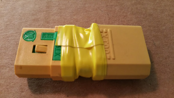
AGREED! Did my first "beta" ride around the block last night and on 6s i was getting spark every time (annoying). I'm planning on the anti-spark xt-90 setup on my final build, but didn't originally include on on this test board... after a few sparks i decided to include a quick anti-spark adapter with these xt-90 anti spark plugs.

GHETTO but works perfectly!
20150614_153400.jpg


Just a quick fix and nice to have a "no-spark" adapter kicking around if i ever need it again. My battery cable on the final build will have this plug built in... Simple and works for 6/8s that i've tried.

HTH!
 
Just got my 10uf caps in. I was able to replace all of them except C43,C44,C49, because they are under the black wire and I don't want to remove it because it requires messing with the gigantic lump of solder that attaches it to multiple components. I'm only running at 6S, so should there be any issues with C43,C44,C49 still being 1uf?
 
Ok, so I am still struggling. Compiled and uploaded the firmware and the bootloader. All is well, looks like everything was done correctly (getting "OK" confirmation ). Now if I try to connect the BLDC tool, but it does not connect to the VECS. Port looks to be the correct one, USB is connected to computer and VECS.
On top of that both STM32 and DRV8302 are getting very hot. Before uploading the firmware they were cool (DRV was a bit warm, STM32 was really cool). 5V and 3.3 V voltages are fine.
Has anyone encountered the same issues? Any thoughts, suggestions?
Thanks!
 
It seems like lots of things have been happening which is nice. I just got back from Denver and have to go on a trip next week again, so currently I don't have so much time. I will try to integrate all the cross-platform updates to the main code branches and test them as soon as I can. It is really nice that the community is starting to get involved with development :)

@lizard
I got your motors and VESC. I tried the 1717 castle motor on a VESC on 25V and the detection worked well. It also ran nicely on my bench, so I don't know what happened when you tested it. I will try to repair your VESC as soon as I have time and send it back to you.
 
jeffpetersen said:
Ok, so I am still struggling. Compiled and uploaded the firmware and the bootloader. All is well, looks like everything was done correctly (getting "OK" confirmation ). Now if I try to connect the BLDC tool, but it does not connect to the VECS. Port looks to be the correct one, USB is connected to computer and VECS.
On top of that both STM32 and DRV8302 are getting very hot. Before uploading the firmware they were cool (DRV was a bit warm, STM32 was really cool). 5V and 3.3 V voltages are fine.
Has anyone encountered the same issues? Any thoughts, suggestions?
Thanks!

It may be your computer that is not allowing you to connect. I just installed bldc tool on a different computer and it isn't connecting even though the port is correct. It is a laptop with a 3g modem so I am thinking that is the issue. However the drv should not get hot, the stm32 will get slightly warm. On my first board I got a blinking red light and drv8302 error, I did another board and it has worked for 5 months now. Never had another board not working other then one that I crossed the pos/neg by accident. Maybe try to build another one from scratch, just learn from your mistakes. Don't apply too much heat to the drv8302, set it to about 300c and don't hold it too close to the chip, keep the air flow at about medium. I put a bit of solder paste on the board beside the chip, when that melts I keep the hot air on it for about another 20-30 seconds to confirm it is connected. Then after it cools down as long as the chip does not budge it should be good to solder the pins.
 
silviasol said:
jeffpetersen said:
Ok, so I am still struggling. Compiled and uploaded the firmware and the bootloader. All is well, looks like everything was done correctly (getting "OK" confirmation ). Now if I try to connect the BLDC tool, but it does not connect to the VECS. Port looks to be the correct one, USB is connected to computer and VECS.
On top of that both STM32 and DRV8302 are getting very hot. Before uploading the firmware they were cool (DRV was a bit warm, STM32 was really cool). 5V and 3.3 V voltages are fine.
Has anyone encountered the same issues? Any thoughts, suggestions?
Thanks!

It may be your computer that is not allowing you to connect. I just installed bldc tool on a different computer and it isn't connecting even though the port is correct. It is a laptop with a 3g modem so I am thinking that is the issue. However the drv should not get hot, the stm32 will get slightly warm. On my first board I got a blinking red light and drv8302 error, I did another board and it has worked for 5 months now. Never had another board not working other then one that I crossed the pos/neg by accident. Maybe try to build another one from scratch, just learn from your mistakes. Don't apply too much heat to the drv8302, set it to about 300c and don't hold it too close to the chip, keep the air flow at about medium. I put a bit of solder paste on the board beside the chip, when that melts I keep the hot air on it for about another 20-30 seconds to confirm it is connected. Then after it cools down as long as the chip does not budge it should be good to solder the pins.

Went through the soldered joints of both DRV and STM32 several times with soldering iron, using plenty of flux. Looks like that fixed the problem! Now the BLDC tool connects with the board, green and blue LEDs are on (only blue one was on before).
Next up is the motor parameter detection...
 
silviasol said:
Yes even though they look soldered well they might not even be connected. I always tin the pins on the chips first, it helps alot.

Ok, the next puzzle: I connect the VESC to computer, fire up the BLDC Tool, hit the "Connect" button. The Tool connects to VESC, I follow the instructions-read configuration, go to Sensorless, read configuration there, hit "Start detection"...
And either 2 of the following happens: the Tool disconnects immediately, red LED blinks once, the VESC reboots. Or I am getting "Fault code DRV8302", red LED blinks 4 times+4 times.
Any idea what happens, what should be done?
Thanks.
 
jeffpetersen said:
silviasol said:
Yes even though they look soldered well they might not even be connected. I always tin the pins on the chips first, it helps alot.

Ok, the next puzzle: I connect the VESC to computer, fire up the BLDC Tool, hit the "Connect" button. The Tool connects to VESC, I follow the instructions-read configuration, go to Sensorless, read configuration there, hit "Start detection"...
And either 2 of the following happens: the Tool disconnects immediately, red LED blinks once, the VESC reboots. Or I am getting "Fault code DRV8302", red LED blinks 4 times+4 times.
Any idea what happens, what should be done?
Thanks.

Some past tips posted not long ago. Check the 3.3V and 5V rails for accurate voltage. Have extra DRV8302s, this is most sensitive part of the build and may need replacement as said by Vedder
 
jeffpetersen said:
silviasol said:
Yes even though they look soldered well they might not even be connected. I always tin the pins on the chips first, it helps alot.

Ok, the next puzzle: I connect the VESC to computer, fire up the BLDC Tool, hit the "Connect" button. The Tool connects to VESC, I follow the instructions-read configuration, go to Sensorless, read configuration there, hit "Start detection"...
And either 2 of the following happens: the Tool disconnects immediately, red LED blinks once, the VESC reboots. Or I am getting "Fault code DRV8302", red LED blinks 4 times+4 times.
Any idea what happens, what should be done?
Thanks.
Hi Jeff,
I also come through the similar problems as you did but finally succeeded with the latest. Like silviasol has pointed out about the soldering, you must be very careful in any aspects like the temperature, the timing, etc. For me, I did damaged 8 DRV8302 so far during the soldering stage. The last one of them can power up, get 5V output for the 3.3V regulator to power up the STM32 but still have the "DRV8302 fault code" to deal with. But I kinda figured out some personal lessons:
1) when soldering the DRV8302 with hot air gun, pay attention to the "rate of change" of the temperature and let the whole board heat up uniformly (be patient) as well as cool down slowly before applying any flux remover (maybe try using it at the end). You can take the damaged DRV8302 to practice soldering the Power Ground Pad. Try using the tin + lead solder instead of the non-leaded one. Apply flux generously and by that I mean as much as it can cover the whole area of the chip. Flux will help holding the DRV8302 in place, distribute the heat uniformly and accelerate the melting process.

2) keep the temperature of the soldering iron at 300-350C. Apply and remove the tip immediately after the solder melt. Again, flux helps a lot. Dont leave the iron on the pad or pins for so long ( more than 5 secs and absolutely not 10sec)
3) if DRV8302 fault code appears, most likely that you have alrd destroyed the DRV8302. Change it with hot air gun. If still cant work, you have to solder a completely new board with all new components. Dont reuse the old components as some of them might be the causes.
4) Sounds silly but dont bend the PCB. I was stupid if enough to clamp the board horizontally so hard during soldering that the PCBs were bent ( this causes fracture in the copper resulting in the DRV8302 fault code)
5) Bypass capacitors and even Inductor might be toast during soldering so check them for failure. It is recommended that you buy components from the BOM.
6) Last but not least, please check before plug in the power. Using multimeter to check for short-circuit between the positive and negative terminals, between the gate, drain and source pins of the transistors, and between the input and output pin of the 3.3V regulator.
Sorry for the long post. Hope this helps.
Martin
 
martinhoang said:
jeffpetersen said:
silviasol said:
Yes even though they look soldered well they might not even be connected. I always tin the pins on the chips first, it helps alot.

Ok, the next puzzle: I connect the VESC to computer, fire up the BLDC Tool, hit the "Connect" button. The Tool connects to VESC, I follow the instructions-read configuration, go to Sensorless, read configuration there, hit "Start detection"...
And either 2 of the following happens: the Tool disconnects immediately, red LED blinks once, the VESC reboots. Or I am getting "Fault code DRV8302", red LED blinks 4 times+4 times.
Any idea what happens, what should be done?
Thanks.
Hi Jeff,
I also come through the similar problems as you did but finally succeeded with the latest. Like silviasol has pointed out about the soldering, you must be very careful in any aspects like the temperature, the timing, etc. For me, I did damaged 8 DRV8302 so far during the soldering stage. The last one of them can power up, get 5V output for the 3.3V regulator to power up the STM32 but still have the "DRV8302 fault code" to deal with. But I kinda figured out some personal lessons:
1) when soldering the DRV8302 with hot air gun, pay attention to the "rate of change" of the temperature and let the whole board heat up uniformly (be patient) as well as cool down slowly before applying any flux remover (maybe try using it at the end). You can take the damaged DRV8302 to practice soldering the Power Ground Pad. Try using the tin + lead solder instead of the non-leaded one. Apply flux generously and by that I mean as much as it can cover the whole area of the chip. Flux will help holding the DRV8302 in place, distribute the heat uniformly and accelerate the melting process.

2) keep the temperature of the soldering iron at 300-350C. Apply and remove the tip immediately after the solder melt. Again, flux helps a lot. Dont leave the iron on the pad or pins for so long ( more than 5 secs and absolutely not 10sec)
3) if DRV8302 fault code appears, most likely that you have alrd destroyed the DRV8302. Change it with hot air gun. If still cant work, you have to solder a completely new board with all new components. Dont reuse the old components as some of them might be the causes.
4) Sounds silly but dont bend the PCB. I was stupid if enough to clamp the board horizontally so hard during soldering that the PCBs were bent ( this causes fracture in the copper resulting in the DRV8302 fault code)
5) Bypass capacitors and even Inductor might be toast during soldering so check them for failure. It is recommended that you buy components from the BOM.
6) Last but not least, please check before plug in the power. Using multimeter to check for short-circuit between the positive and negative terminals, between the gate, drain and source pins of the transistors, and between the input and output pin of the 3.3V regulator.
Sorry for the long post. Hope this helps.
Martin

Martin, thanks for the advise. I'll try to be more careful while soldering the DRV, hope that will work.Though my previous experience with DRV in other controllers was not that bad, but maybe I just was lucky.
 
jeffpetersen said:
Or I am getting "Fault code DRV8302", red LED blinks 4 times+4 times.
Any idea what happens, what should be done?
Thanks.

That is exactly what the first one I did had done. My advise is move onto another board and pull off the expensive chips from that board. A fail safe way for the drv8302 chip is to heat the board up from the bottom. These circuit boards are very good quality, as good or better then the computer motherboards I repair and they have withstanded over 200c for unleaded solder, to melt leaded solder you won't need the board hotter then 180c. This temp will not damage the board and this way the drv8302 is staying as cool as possible. While doing this the danger is if the heat is not even on the board, monitor the temp(you can get a type k thermometer for under $10 on ebay), don't heat the board up too fast, that can crack the layers inside the board from uneven heat. I use a infrared heater to do mine like shown in my for sale thread http://endless-sphere.com/forums/viewtopic.php?f=31&t=68421 but using a hot air under the board will work the same. However I had to replace a drv8302 once and having my wand at 300c worked perfectly, I even heated it up fairly quickly, I am still using that vesc without any issue's.
 
Here is a video where I replace a DRV8302:

[youtube]O7vaW27kdLo[/youtube]

I had my hand in the way most of the time, but I didn't want to desolder and resolder the chip again just to remake the video. I did not pre-heat the board and had the hot air set to 350 degC (I think my ebay hot air station gives lower temperature than I set). I think I have done this more than 100 times already and it works in 95% of the cases for me, but I'm sure that you get better reliability if you pre-heat the board and try to follow a temperature profile properly. I'm always using leaded solder since it has a lower melting point, is easier to handle and gives better results.
 
I know no one has asked this question. How does one go about removing flux from the VESC after resoldering. I only have rosin base soldering flux which is tacky. I was thinking of dunking it in a bath of 99% isopropyl alcohol to clean it.
 
Back
Top