puchwudi
10 mW
- Joined
- Mar 19, 2015
- Messages
- 34
Hello guys!
This is my first post in the ES community I really love this platform!
About two months ago, I was thinking about a new project for myself. Soo I got the idea to convert an old Puch Maxi to an elctric offroad bike. My goal is to imporve my knowledge about electromobility and to show off what i learned in the last years..
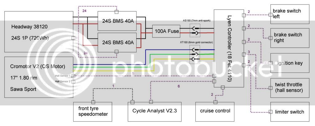
Main Electronik components:
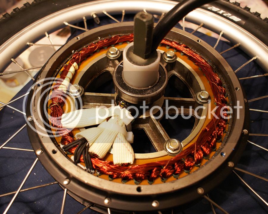
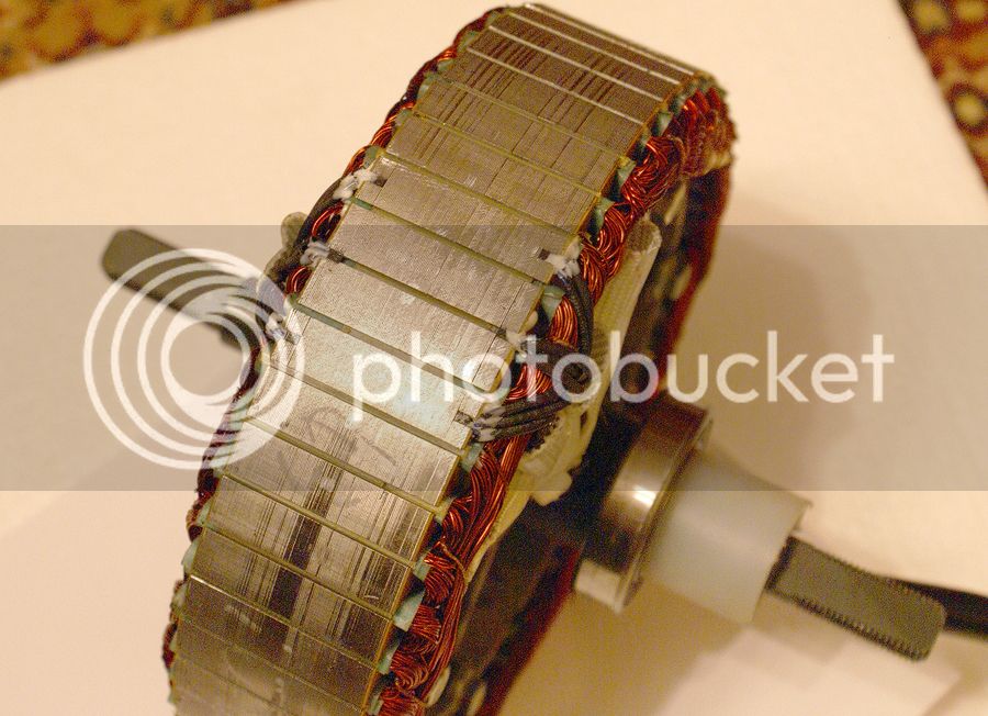
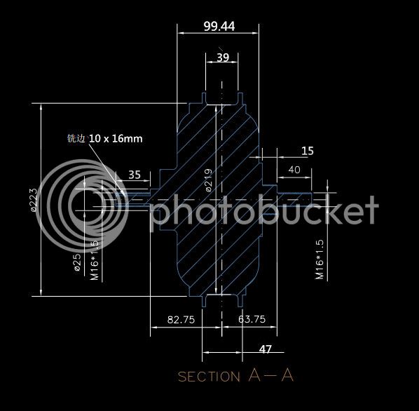
- Cromotor V2 (QS Motor)
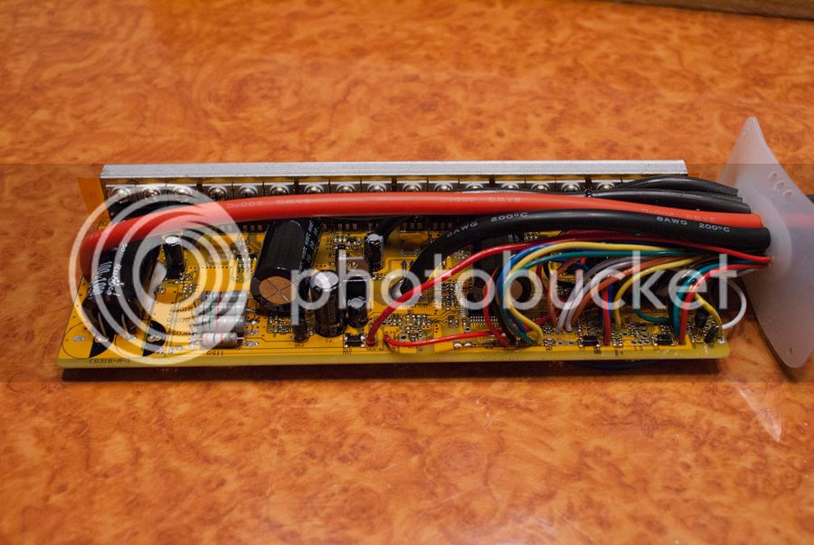
- Lyen 18FET controller (eb318)
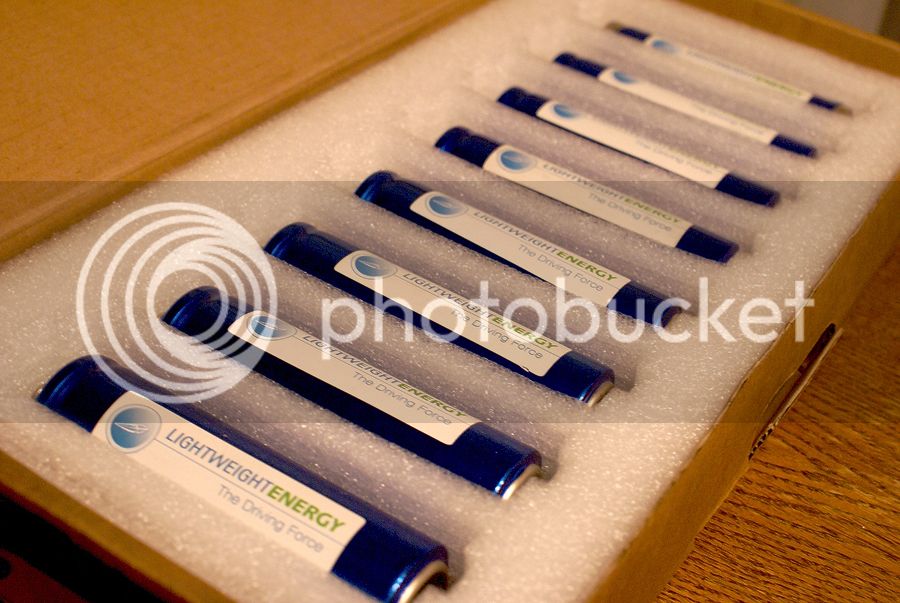
- Headway 24S1P (38120)
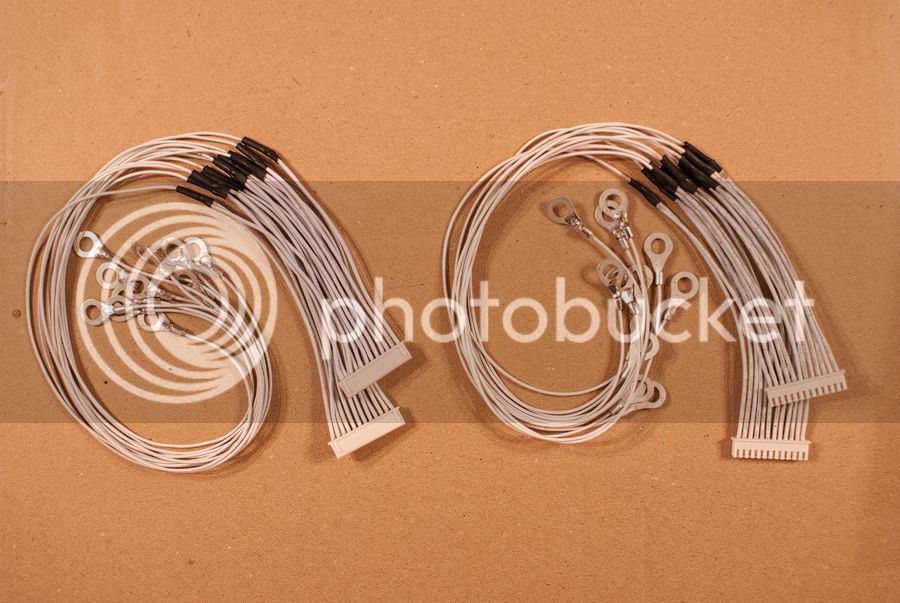
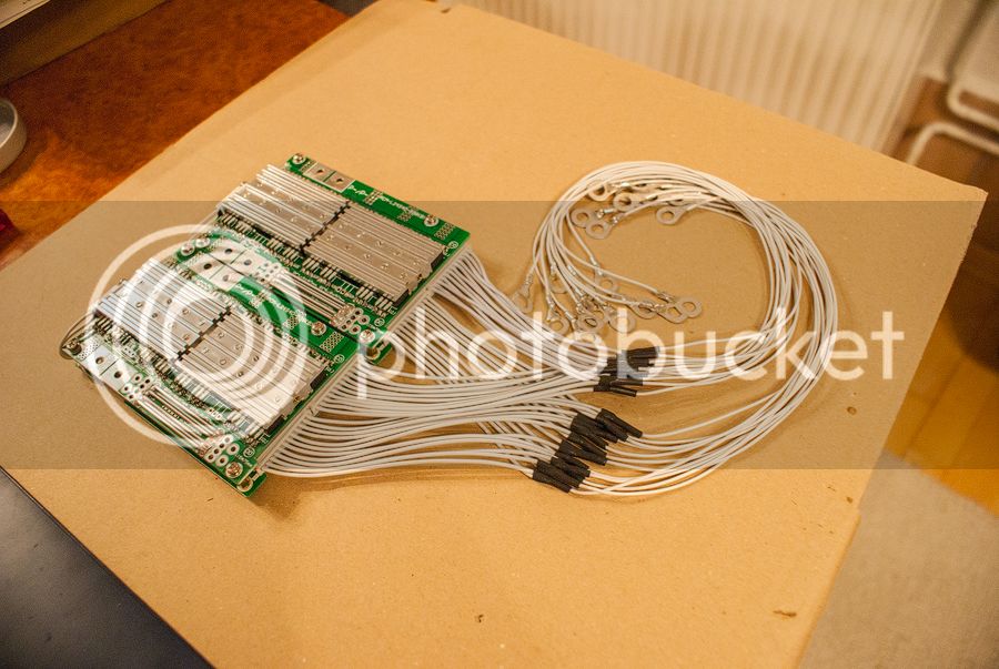
- 2x 24S 40A BMS (leadyo battery)
- TCM-400 24S Carger (4A cont.)
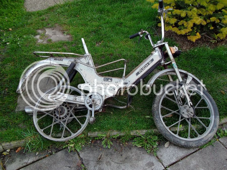
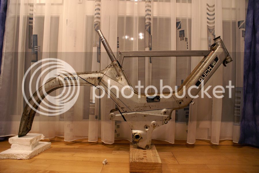
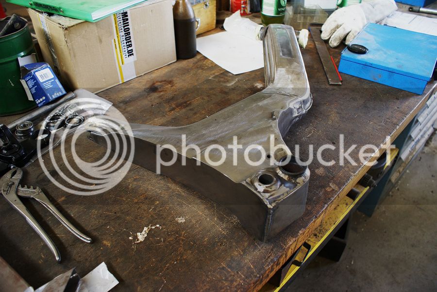
My father brought my a rusty and dirty frame, as a present from his chief to me. This was motivation enough for me to create a nice bike
_____________________________________________________
READY TO RUN! (25_10_2015) But go on reading!!! = )
Micro Update March 2023


_____________________________________________________
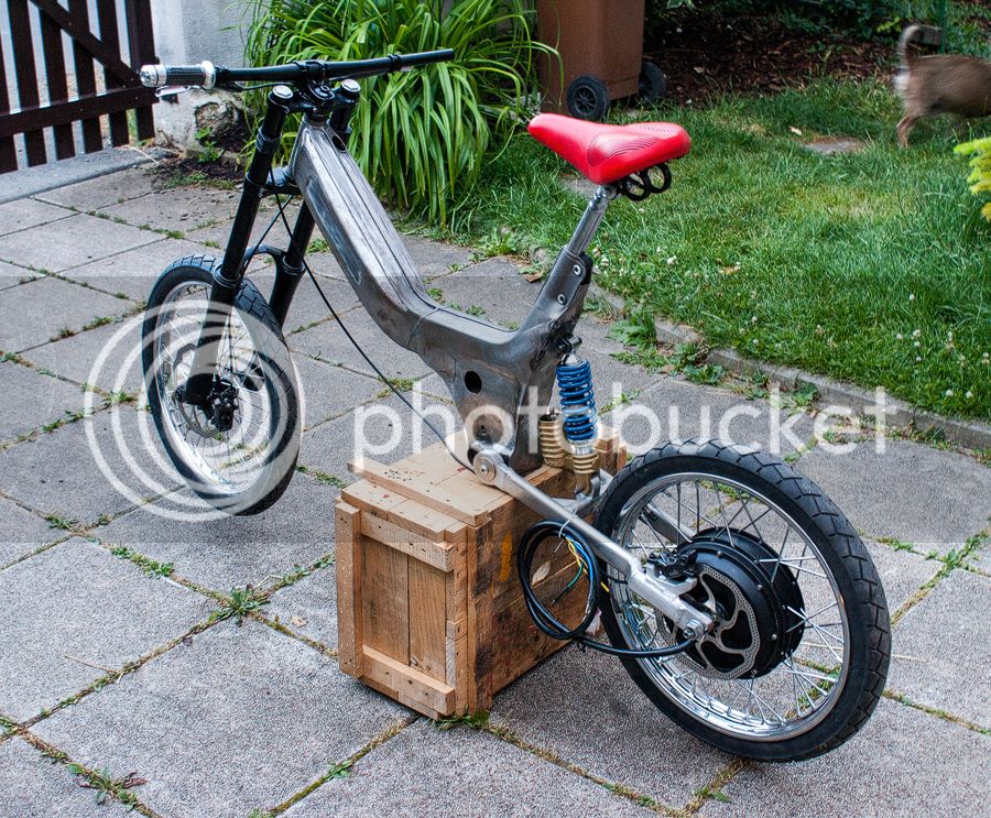
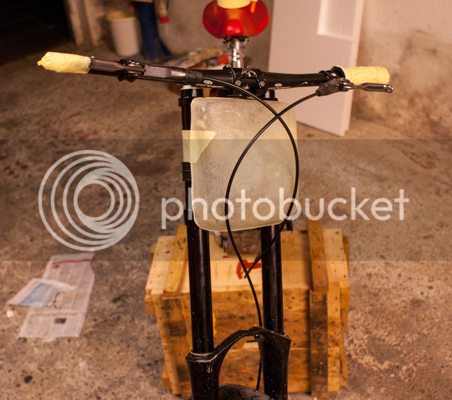
I threw away all the redundant parts and cleaned up the frame. the first things I was thinking about ... Where can I place the battery? Well the bike has a gas tank on the front side of the frame, which is integrated in the whole mechanical construction. removing or opening this would decrease the mechanical strength of the frame...So I am place the battery pack between the steering head bearing and the socket for the seat.
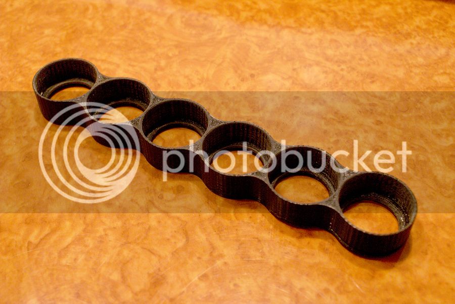
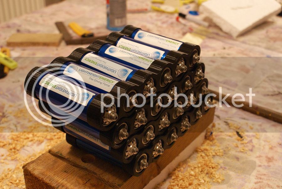
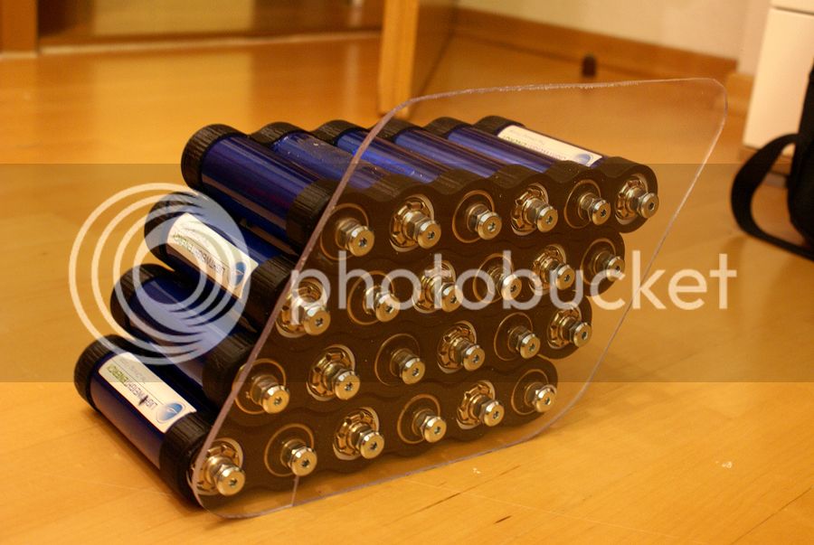
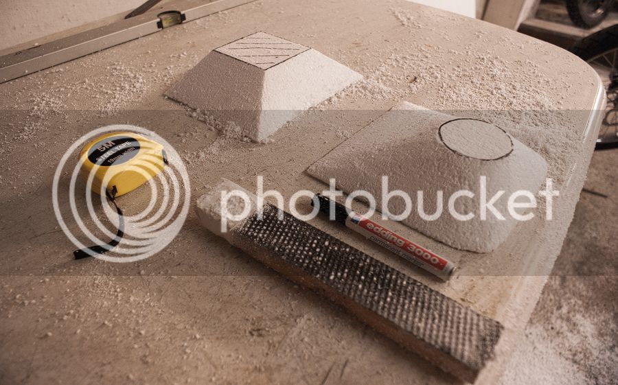
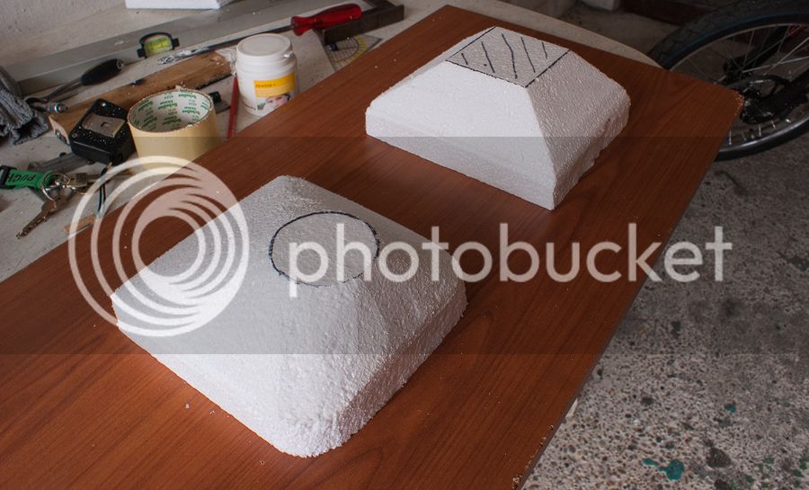
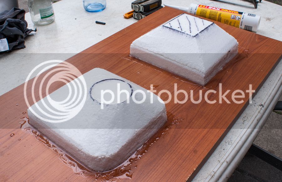
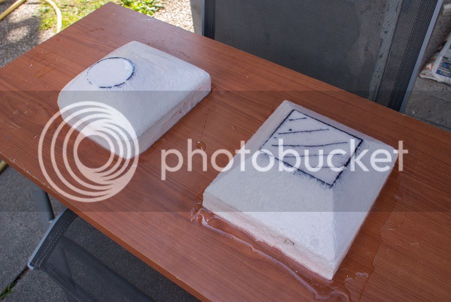
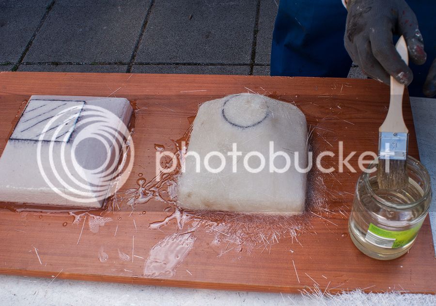
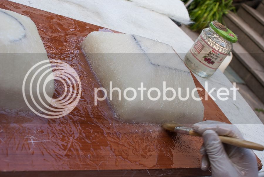
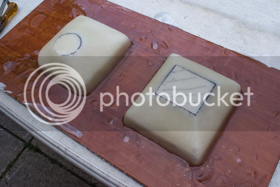
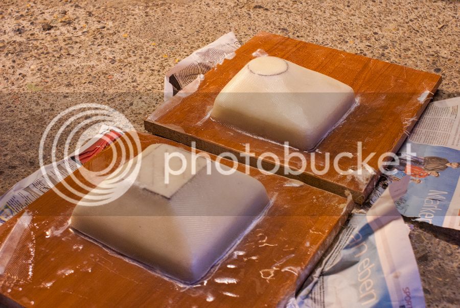
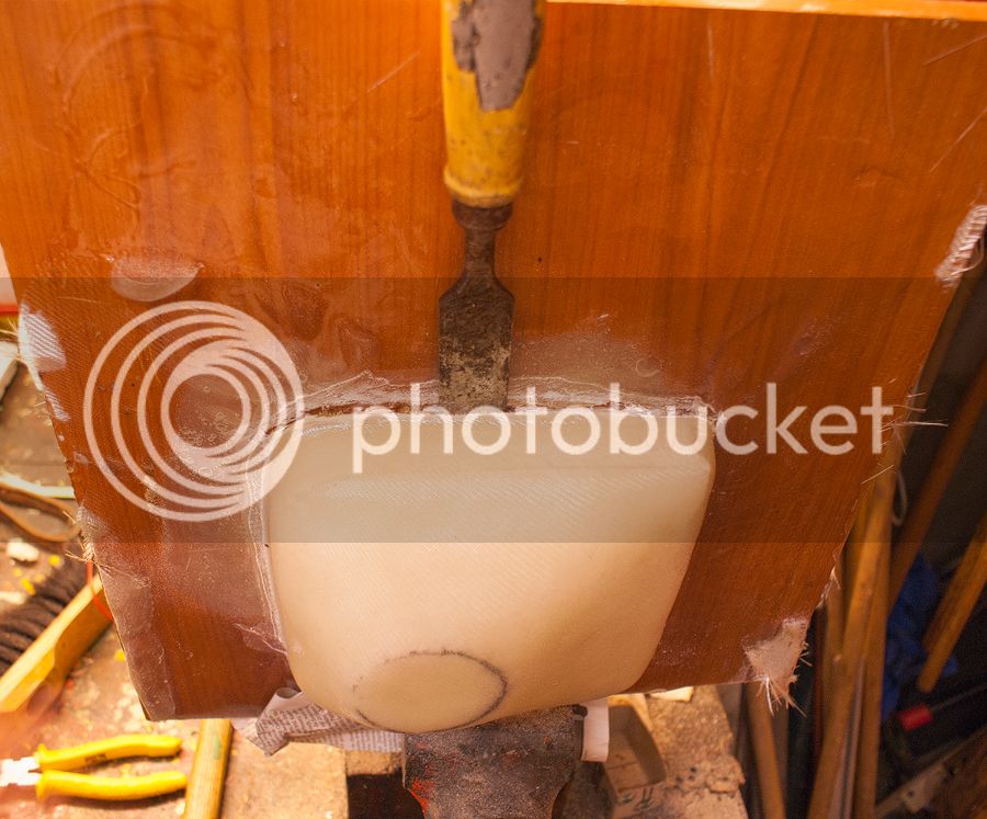
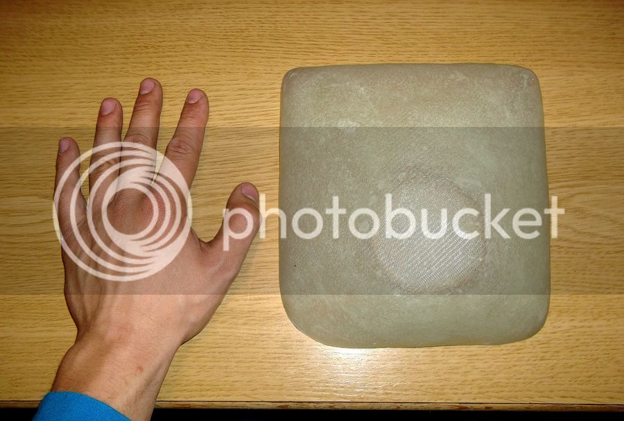
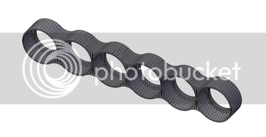
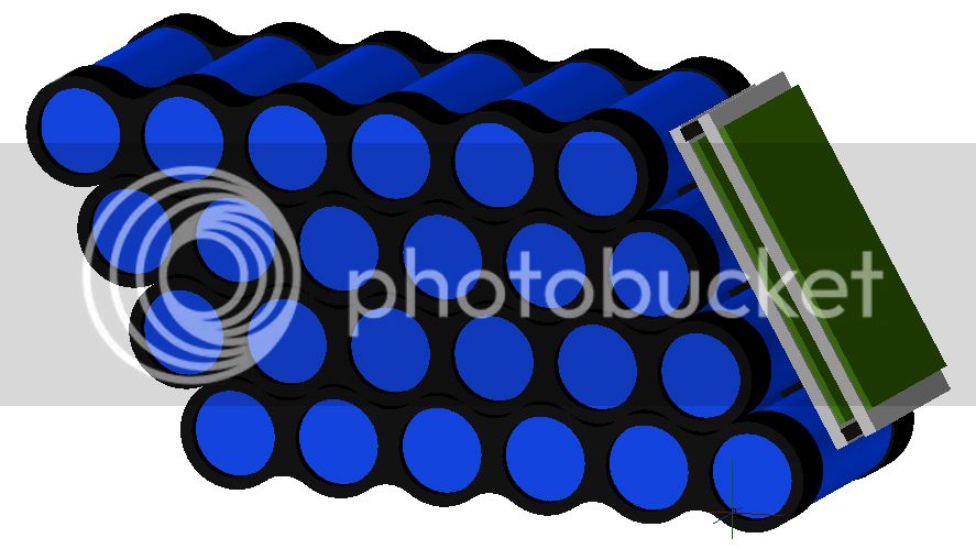
The next steps was to plan the design of my Headway pack. I use the single cells in a row, as you can see. The plastic holder are build by a 3D-Printer.
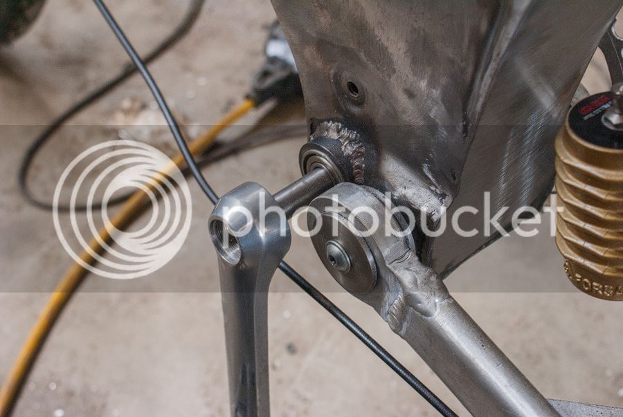
In the meantime I got to know a nice guy, which supports me with all the mechanical / welding work, so we cleaned the frame to a delight version
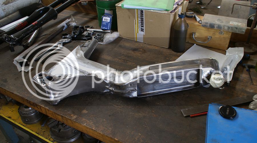
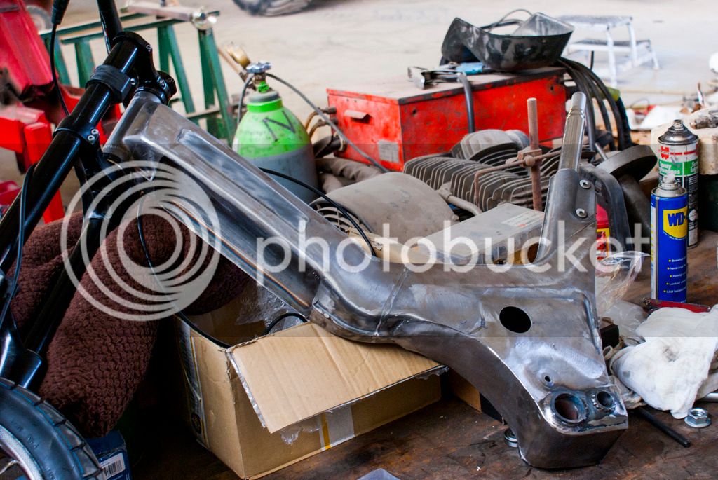
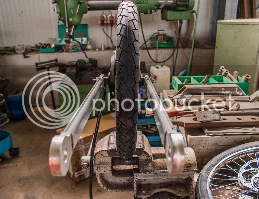
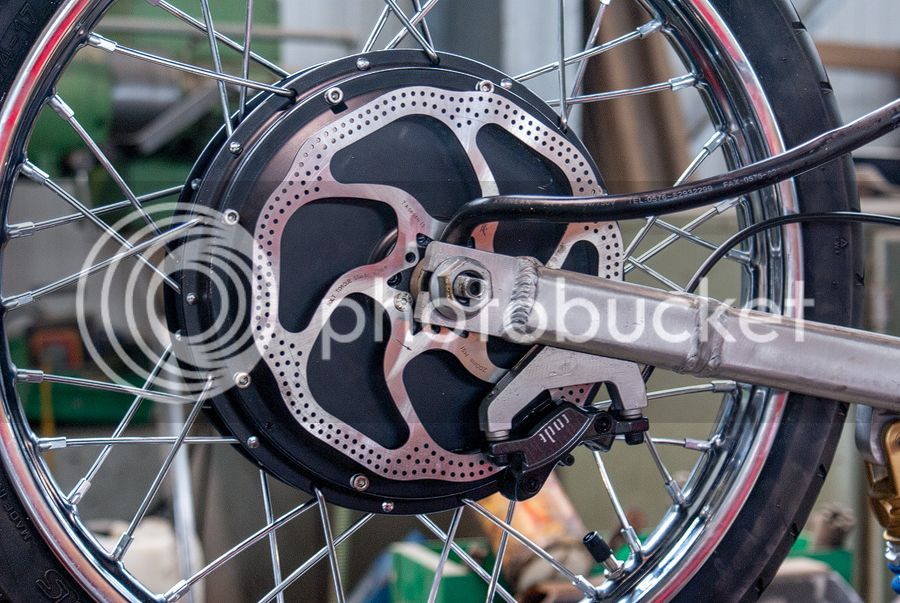
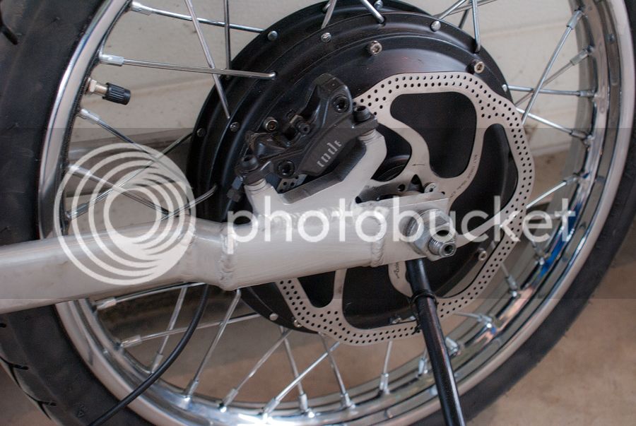
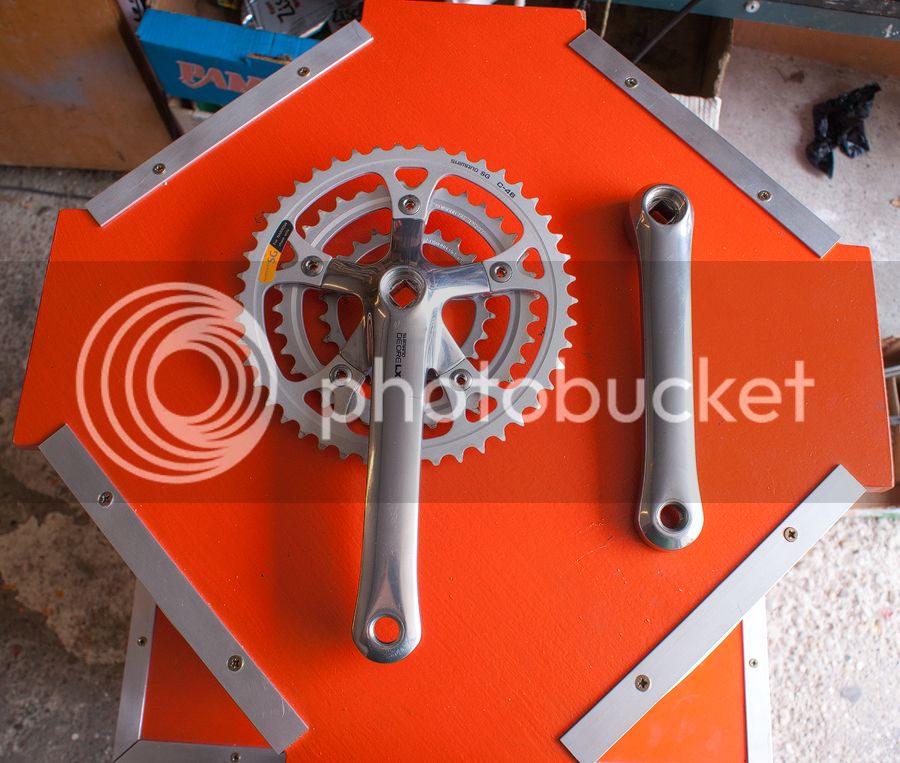
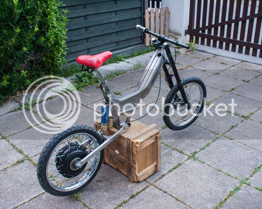
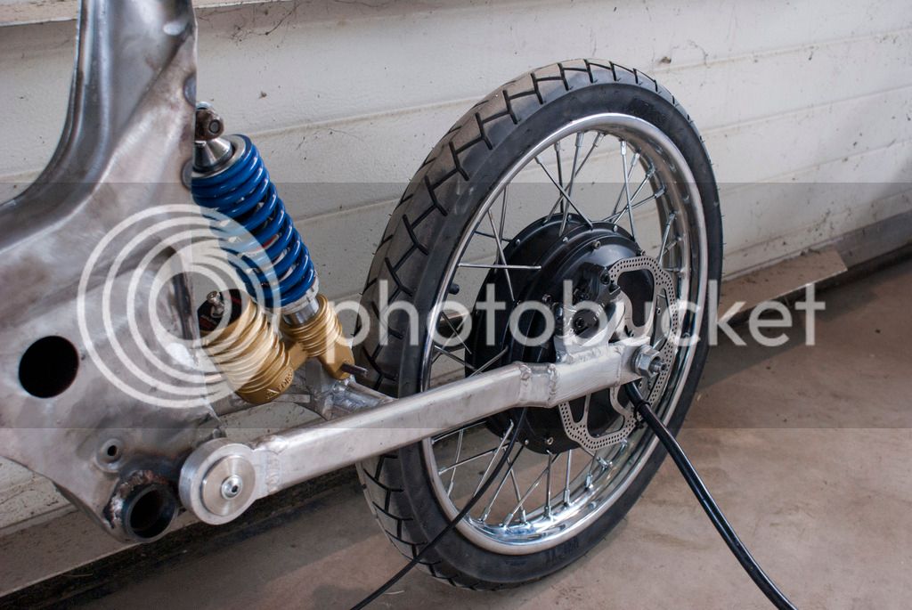
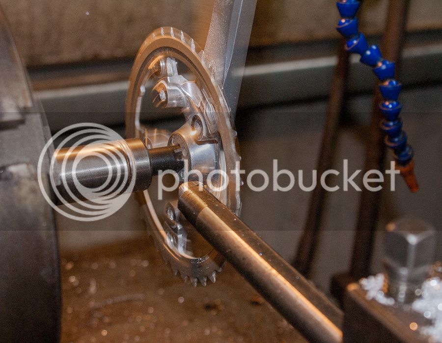
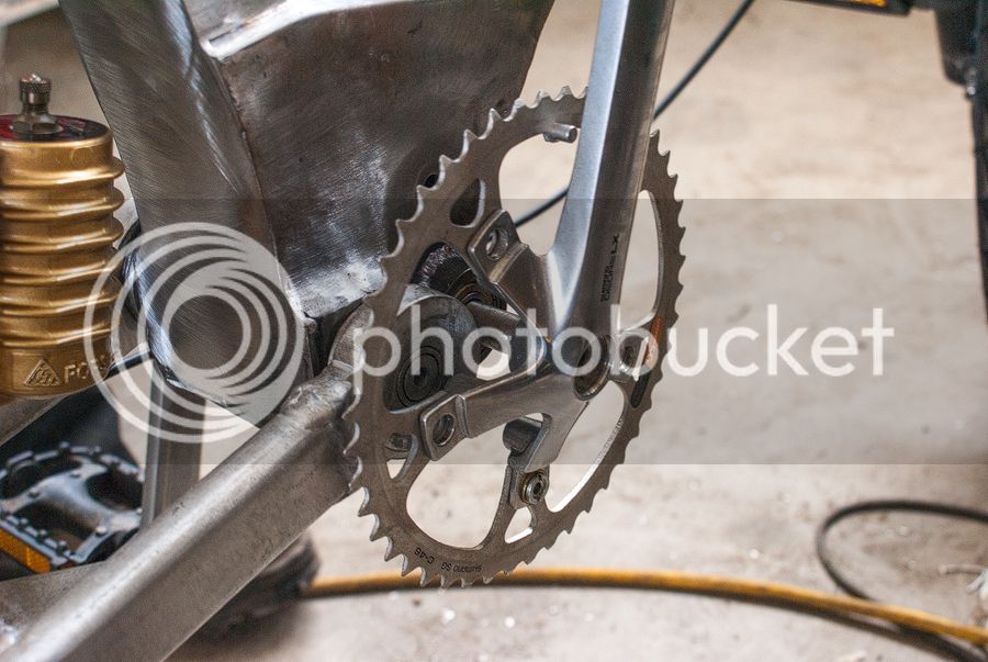
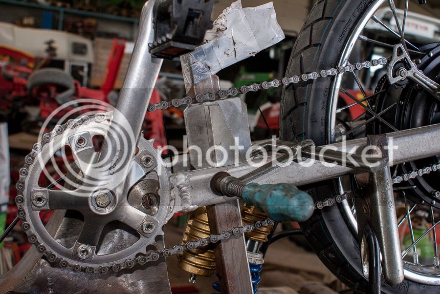
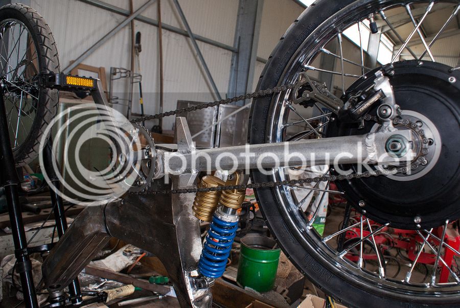
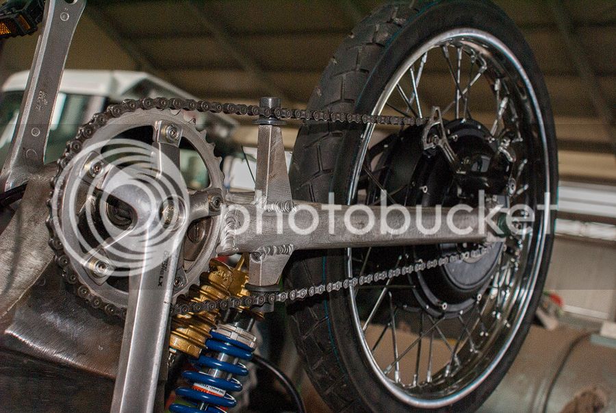
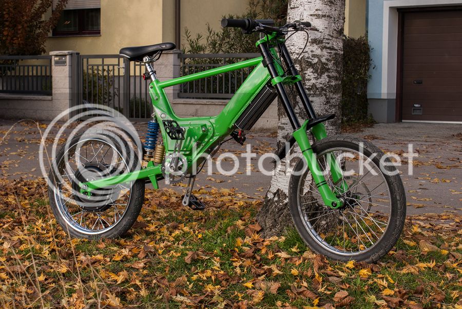
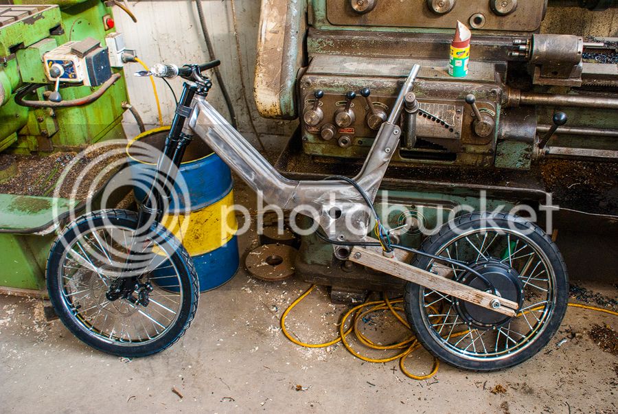
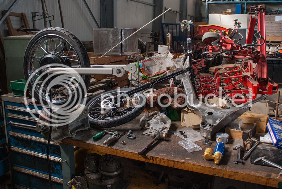
So the frame got a second axle for the bike crank. The front suspension is a Marzocchi
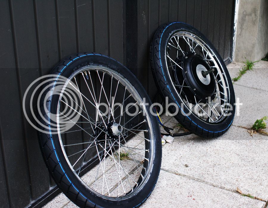
888 VF2 with the 20mm axle. A good friend of mine mounted the tires on the rims and fitted the cromotor. My spokes are 4mm thick, so at the back I use a 17" rim (1.80") and at the front a 17"(1.20") with Sawa Sport tyres
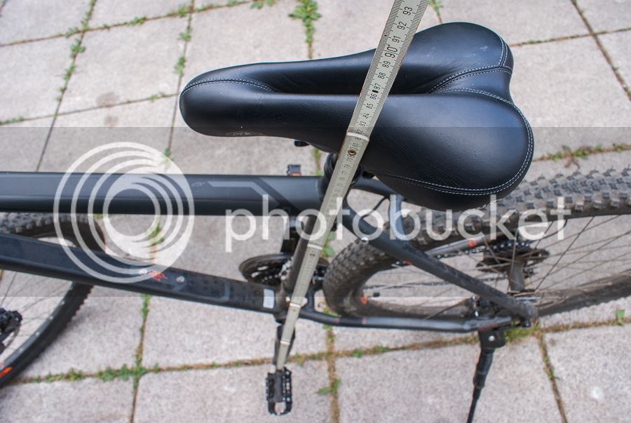
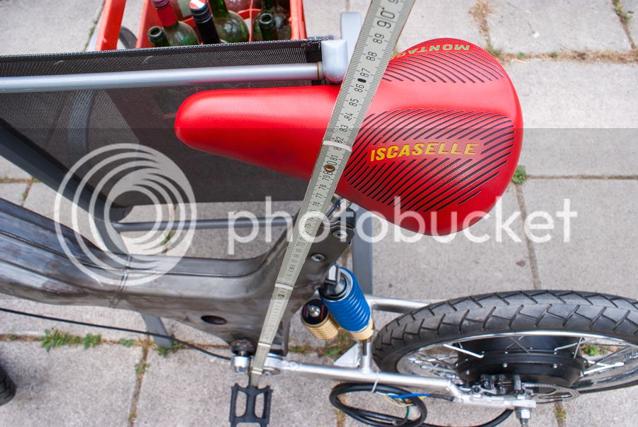
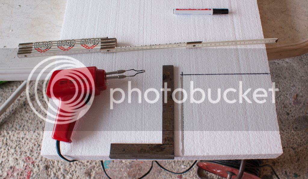
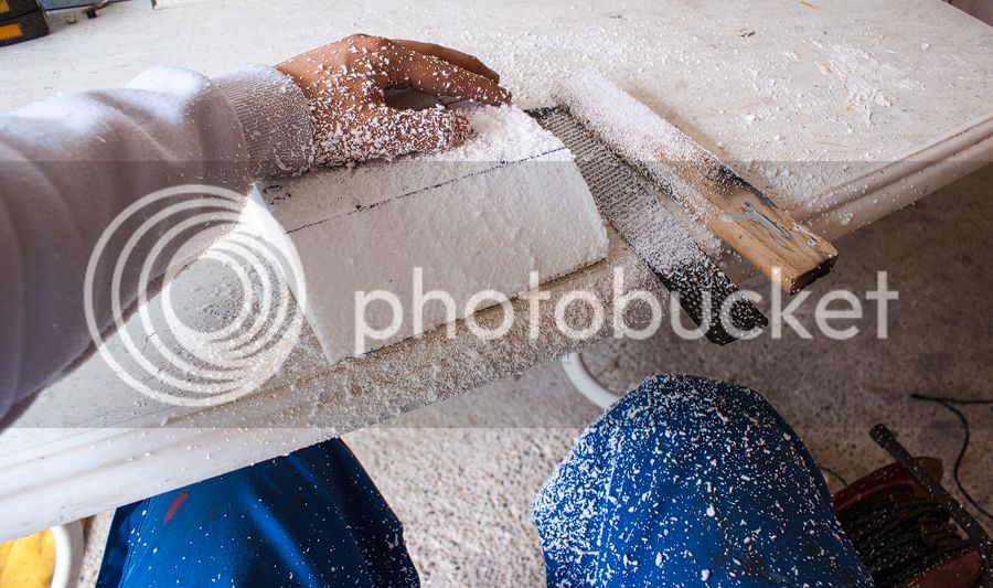
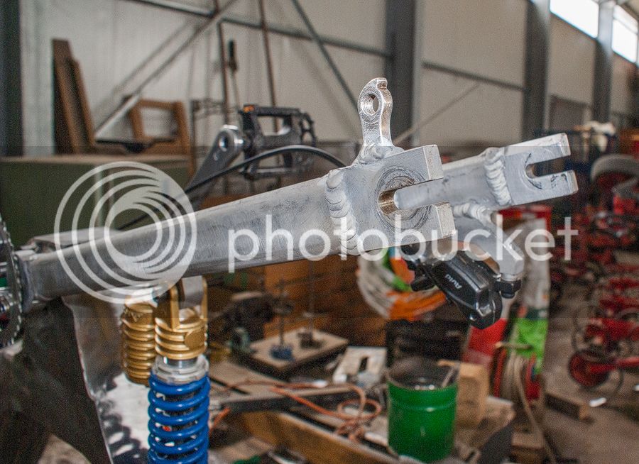
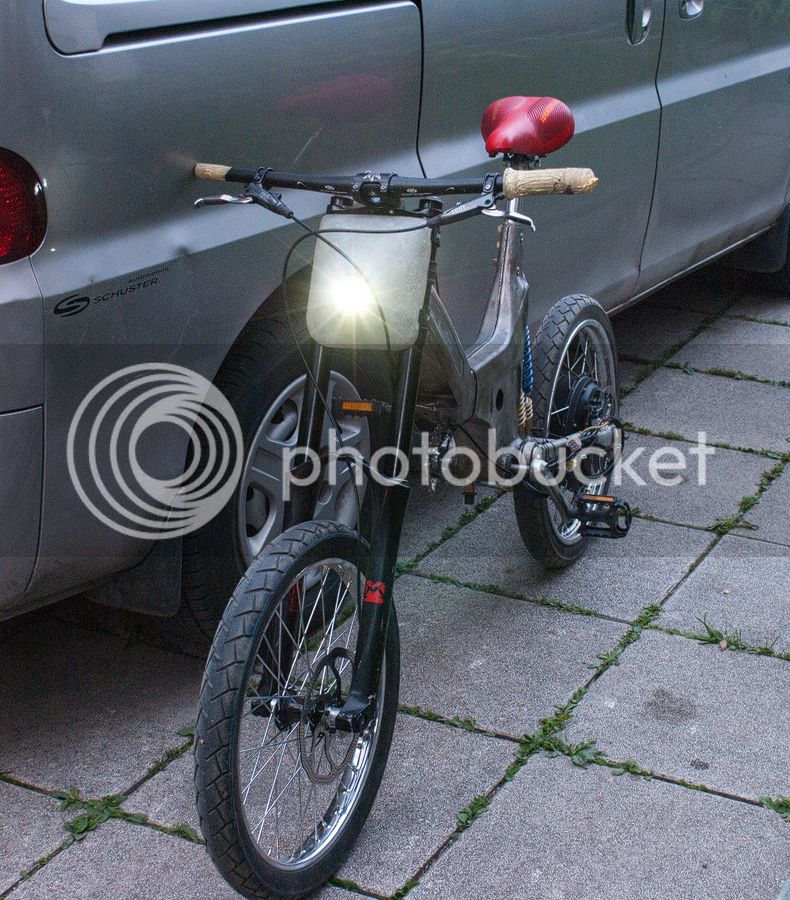
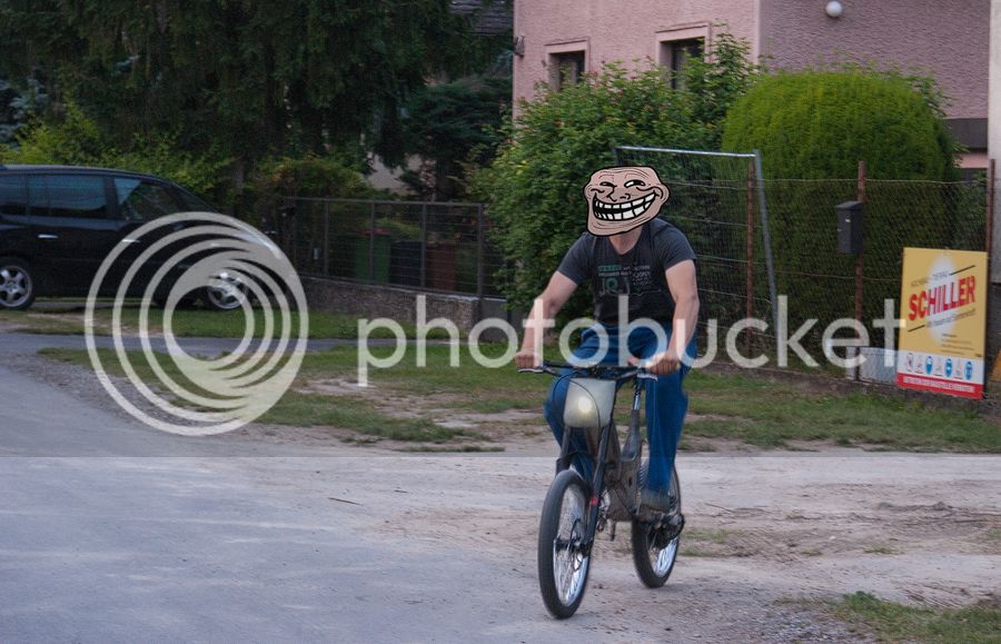
Well after getting the frame and tyres ready, we started with the lever out of wood for checking the poition of the seat and so on...
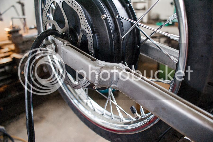
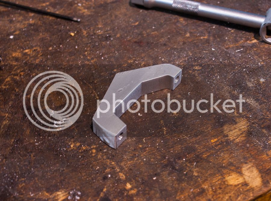
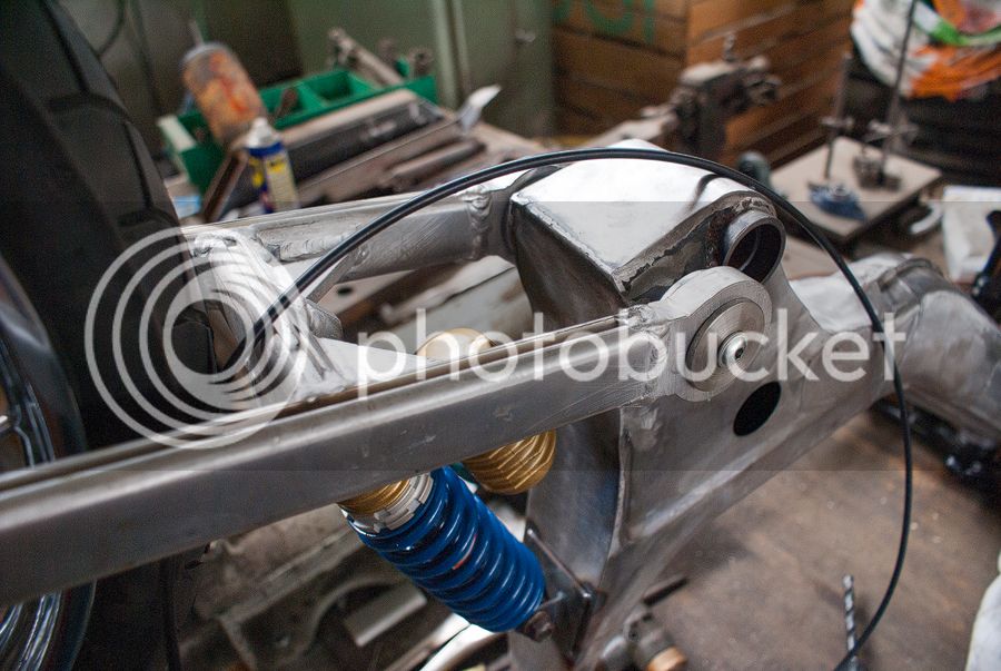
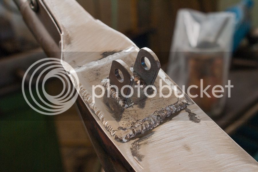
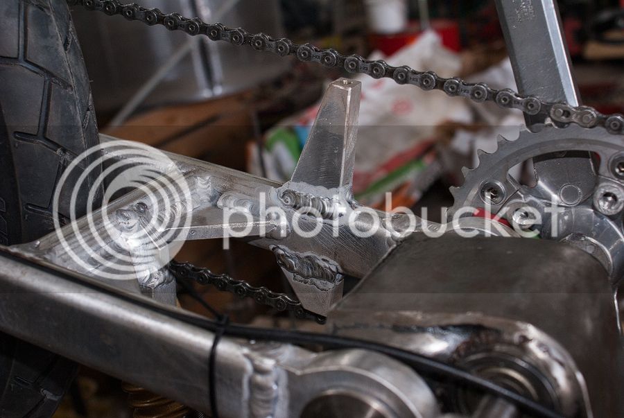
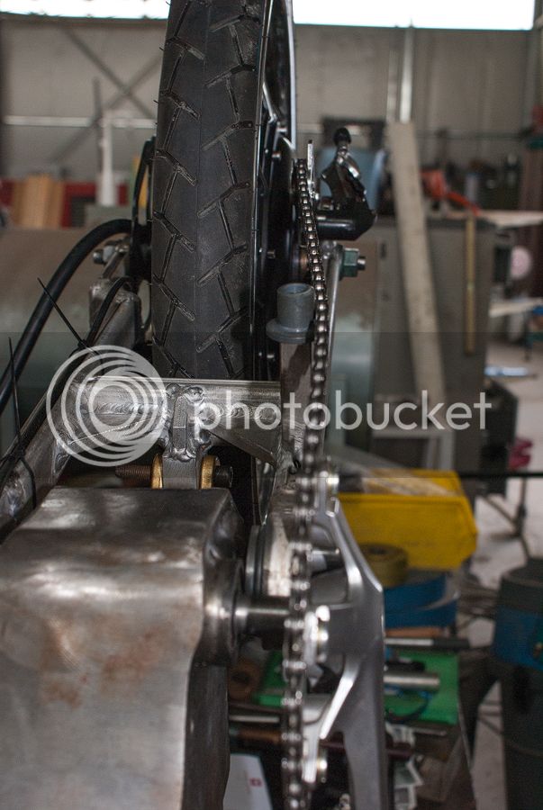
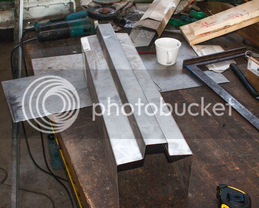
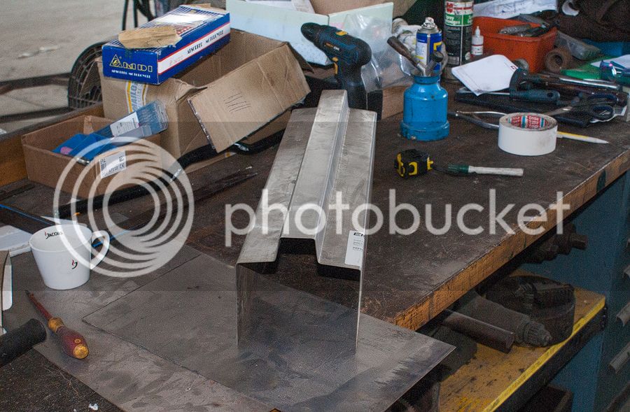
The lever consists of a very robust aluminium profile which is welded with very strong drop outs for the Cromonster.
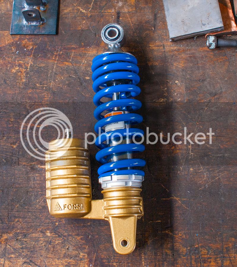
I hardly found the perfect fork for our frame, so we used a scooter fork with an extra gas bottle where you can choose the strength of the bumper.
We left the workshop at 6 pm today
In the following days I will upload some electronic pics :lol: :lol:
I will keep you UP to DATE
This is my first post in the ES community
About two months ago, I was thinking about a new project for myself. Soo I got the idea to convert an old Puch Maxi to an elctric offroad bike. My goal is to imporve my knowledge about electromobility and to show off what i learned in the last years..
Main Electronik components:
- Cromotor V2 (QS Motor)
- Lyen 18FET controller (eb318)
- Headway 24S1P (38120)
- 2x 24S 40A BMS (leadyo battery)
- TCM-400 24S Carger (4A cont.)
My father brought my a rusty and dirty frame, as a present from his chief to me. This was motivation enough for me to create a nice bike
_____________________________________________________
READY TO RUN! (25_10_2015) But go on reading!!! = )
Micro Update March 2023
_____________________________________________________
I threw away all the redundant parts and cleaned up the frame. the first things I was thinking about ... Where can I place the battery? Well the bike has a gas tank on the front side of the frame, which is integrated in the whole mechanical construction. removing or opening this would decrease the mechanical strength of the frame...So I am place the battery pack between the steering head bearing and the socket for the seat.
The next steps was to plan the design of my Headway pack. I use the single cells in a row, as you can see. The plastic holder are build by a 3D-Printer.
In the meantime I got to know a nice guy, which supports me with all the mechanical / welding work, so we cleaned the frame to a delight version
So the frame got a second axle for the bike crank. The front suspension is a Marzocchi
888 VF2 with the 20mm axle. A good friend of mine mounted the tires on the rims and fitted the cromotor. My spokes are 4mm thick, so at the back I use a 17" rim (1.80") and at the front a 17"(1.20") with Sawa Sport tyres
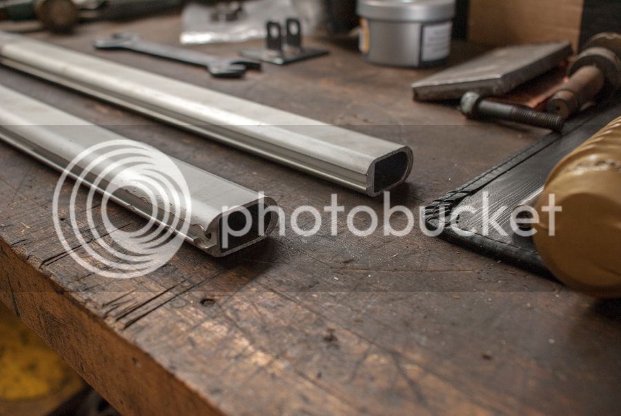
Well after getting the frame and tyres ready, we started with the lever out of wood for checking the poition of the seat and so on...
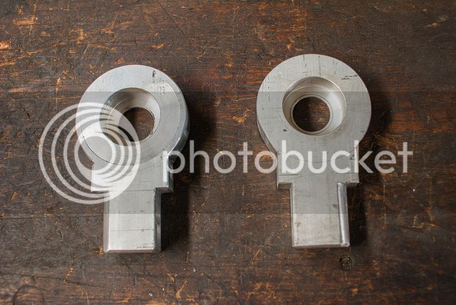
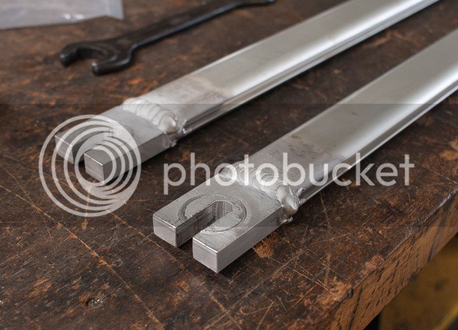
The lever consists of a very robust aluminium profile which is welded with very strong drop outs for the Cromonster.
I hardly found the perfect fork for our frame, so we used a scooter fork with an extra gas bottle where you can choose the strength of the bumper.
We left the workshop at 6 pm today
In the following days I will upload some electronic pics :lol: :lol:
I will keep you UP to DATE
Last edited: