Definitive Tests on the Heating and Cooling of Hub Motors

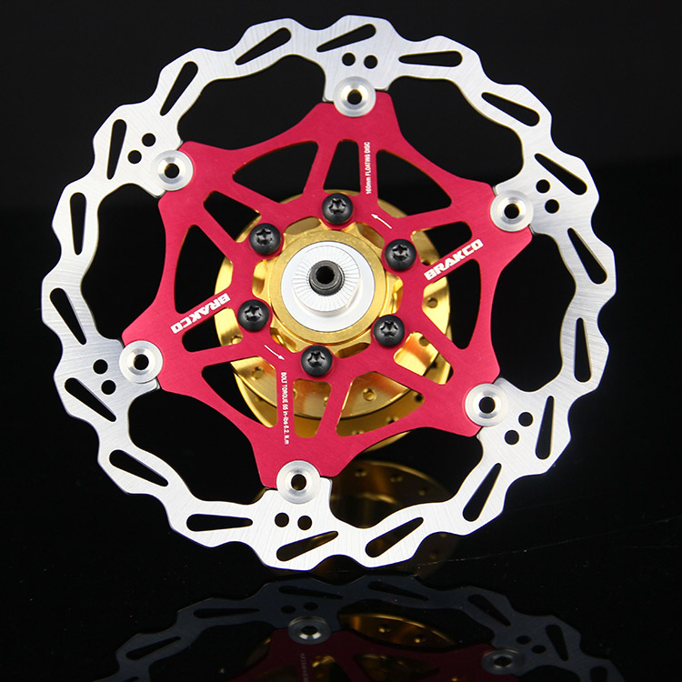
The bicycle disk trend is moving toward a large center hub mounted type rotor. Lots of options for mounting around the outside of a huge bearing.
avid_hsx_disc_brake_rotor_bicycle_6_bolts_160mm.jpg

absoluteblack-raven-sl-centerlock-rotor-95g-1.jpg

New-Brakco-mountain-bike-MTB-Disc-font-b-Brakes-b-font-Floating-font-b-Rotor-b.jpg
 
One of those with a pin fin heatsink filling nearly the entire internal area between the axle and the rotor would look cool as hell!

Like one of these:

12a77e1.jpg


They would be a nice option because the pins could be manufactured proud of the dropout face if necessary, and trimmed to fit the particular application front/rear to clear the forks or stays. They are non-directional so they wouldn't look "odd" like an extruded fin would in various mounting positions on the bike.

edit: I have a CC-400 current load device that uses this style of sink. It's about 4"x4" and effectively sheds that rated 400 watts with a decent fan mounted, sufficient to keep the MOSFETS happy... I think the Deg C/watt improvement with the available area could really help with downsizing hub motors in moderate applications, with the high density motors using liquid to move the heat to a better location for cooling. I'd love to see where W/kg could be maxed out on hubbies...

edit2: I was just thinking, this large bearing idea also gives some pretty damn good ways to optimize the torque arm business, rather than relying on the relatively small diameter axle flats...
 
speedmd said:
One thing to consider is the twofer you can get with such a left side heat sink/ cooling concentration as it could vented/ducted in a way to help cool the rotor also.


Sorry language barrier here - could you try to explain what you said with different words?
Do you mean that such a fin attached to left side cover would create so much extra thermal mass also close to copper/magnets that the heating/cooling would create some sort of drag inside the motor to further improve cooling? But that would mean open/unprotected motor with ventilation holes at least at one side of the motor, maybe both sides. With chances of water & debris entering motor.
 
No, the fins would actually be attached to the stator/axle and not rotate with the wheel. Speedmd is saying that if you run a duct system along the left side, it serves double duty as a rotor cooling shroud as well. So you get a motor bonus and a brake bonus by ducting air across that side of the motor. Cool idea!
 
Not sure I follow you. Connected to the axle you say. But a steel axle is a poor conductor. Would it not be wise to set the added thermal mass to use? I mean attached to cover fin would spin. Attached to axle it would be stationary? And heat would be transferred via axle mounting point only?

If you cut a center hole in the heat sink the size of the axle and epoxy it to side cover it would spin and be air cooled when riding, adding massive thermal mass/surface area. Heat would pas quickly thru the alu side into fin and get rapidly cooled by air as the wheel spin.

Too much beer tonight I think I will try to re read this thread tomorrow after i find my reading glasses and my little dictionary cos I a little lost in translation here I think :D
 
Lol yeah, the axle would remain steel, but the main design change is to move the bearing from a small one on the axle to a much, much larger one that allows for an aluminum heat sink to poke through, around the axle. The outer surface of that aluminum heat sink would then be where the bearing/bearing race would be installed. That was the point of the brake rotor with a larger internal bolt circle - so it can mount to a motor side plate that effectively has a a giant 3-4" hole in it. All of this is possible just by solving/making a cost effective large bearing assembly on that side.

edit: The primary advantage of the large bearing allows a large, short path for thermal conduction from the stator winding region to the "outside world" - it removes the inherent limitations of having a multi-step radiant heat path to follow.
 
The right side has to deal with the freewheel /free hub constraints but the left side only has to deal with the brake rotor. This gives you much more opportunity to enlarge the bearing in the case cover and still mount a larger bolt circle rotor to the case with a finned /fan type mount and surround the stationary heat transfer center block. Lots of details to work out, but could easily see the transfer block having both air passages/fins or water cooling options as well as a great place to add a torque plate/arm. It also gives you much more room for fat wires to exit . Too many benefits to ignore this option IMO. In a green field approach, the stator would have this massive heat transfer block cast into it with proper heat flow taken into account.
 
justin_le said:
Ah sorry, I thought I saw some posts to the effect of just purely internal fans without additional vent holes but may have construed that in my mind from reading too quick! At low to moderate RPM's there's no doubt that would be a big boost over trying to passively encourage air flow through holes in the plates from just the motor rotation. Previously I was put-off by the idea of active powered fans in the hub before as being inelegant, but that's a bit of prejudice. In practice this seems like a very sensible and inexpensive approach, and as you say remains equally effective at super low speeds which is often the case when hub motors are at their maximum load on those long steep hill climbs.
Indeed you hit the nail on the head there Justin...a few of the many reasons I gave this a go to begin with. I don't have many tools, or cash to throw at fancy setups, but simple cheap fans I can do. :)
I'm still yet to do proper, graphed testing, but today just did a quick test in the backyard.
http://endless-sphere.com/forums/viewtopic.php?f=30&t=56965&p=1072763#p1072763
[youtube]Bw0G3Z1bzx0[/youtube]
The rate the temp drops when the fans are running shows pretty clearly how effective they are. :)

Cheers
 
madin88 said:
i have some questions:

i would like to see the fins you installed inside the MXUS :) could you post a pic?

In theory yes, but I'm having a hard time finding where the experiment setup pics got stashed. :oops: The fins were just simple vanes of thin cardboard that were cut to in profile to just fit without rubbing against the stator, I think we had 8 or 9 vanes on each side, running radially, and glued into place with a thin strip of epoxy.

did you only painted the sidecovers or the entire inside incl stator, windings and magnets?

We painted both the inside of the side covers and the sides of the stator and stator windings, but we didn't paint the magnets or the face of the lamination teeth facing the magnets. I guess that was a bit of an oversight, since all told the magnets and facing stator teeth add up to a total surface area that is roughly equivalent to the area facing a side plate. Painting everything would have increased the total black painted surface area by 50%, so as a rough estimate you could assume that the difference between painted and unpainted would have increased by another ~50% or so had it all been done.

you have tested one MXUS with black paint and another with fins, right? not one with both mods?

Correct. These modifications didn't have a huge effect, about 6% conductivity increase for painting black (could have been ~9% if we painted everything), and about 12% for adding the fins. Presumably with both modifications it would be additive to a ~20% overall improvement in thermal conductivity. Again it's not huge, but it's also an improvement you can get with almost zero cost to the manufacturer and no external changes to the hub.

I mean, if the motor design is currently relying on just passive convection and radiation to move the heat generated in the stator out to the side plates, then they might as well do the obvious steps to help optimize that heat flow no?

during the high power tests you have pushed to core to 100°C, what was the temperature during the low power test?

Good question. Because the low power tests were done just using the normal core losses from running the motor unloaded in order to generate the core heat, the actual steady state temperature was very much dependent on RPM. With the MXUS hub for instance, a the At the low 100 rpm run the core was only generating 7.5 watts on average of internal heating so the hub only reached 31 oC, while the same motor at 500 rpm was dissipating 52 watts and reached 56°C. That's why if you look at the error bars on the low power graphs you'll see they are much larger at the low RPM range, since the relative uncertainty in the temperature differences is a lot greater when the core and shell temps are close together.

We were trying in this approach to find a technique that would be easy for someone without a bunch of lab equipment to do at home. IE, hook up a CA3 to their motor with an internal temp sensor, use the CA's speed feedback to set the RPM limit of the hub and run it unloaded until temperatures stabilized. Then with the CA3's temp data and an inexpensive IR sensor on the motor side plate anyone could produce similar Conductivity vs RPM graphs. However in the end the data is cleanest and most consistent when the motor core is at the same temperature across the range of RPMs, and to do this requires either loading the hub during the test or (as we did) using a field oriented controller with large amounts of field weakening current to greatly increase the I^2R copper losses without needing an external load.
I've attached some spreadsheets as an example of the raw data if you are interested.

I would like to do some calculations, but i'm not totally sure if i interpret the graphs right. could you please help me or tell me if i do it correct?
Ok, the vertical line shows conductivity in watts/°F between stator and shell and the horizontal line shows how much influence the rpm have.

Close. It's in watts / Kelvin which is the same as watts / °C, We've still got feet and inches but Fahrenheit temperature scales have been effectively demoted in Canada for many decades now, and I'd suggest it would be best to keep all temperature discussion units here in SI units as well so numerically everything is consistent.

During the high power tests the stator has 100°C and shell stays at maximum 65°C in steady air, so the delta T is 35°C.
now the math for MXUS at 300rpm (without mods):

So if you kept things in Celcius or Kelvin everything would have been spot on, but as it is you've introduced an error of 9/5th. In Fahrenheit the conductivity would be just 1.8 W/°F, as opposed to the 3.3 number you pulled from the graph.
 
Cowardlyduck said:
I'm still yet to do proper, graphed testing, but today just did a quick test in the backyard.
http://endless-sphere.com/forums/viewtopic.php?f=30&t=56965&p=1072763#p1072763
The rate the temp drops when the fans are running shows pretty clearly how effective they are. :)

This is a good test and will be nice an easy to quantify. For comparing relative effectiveness of fan vs. no fan just time how long it takes to drop from say 80 degrees to 70 degrees in each case. But you can also get absolute values of conductivity by using the time stamp on the video to plot the temp vs. time plot. Weight your stator core and use the estimates from this post here (~0.50 Joule / gK):
http://endless-sphere.com/forums/viewtopic.php?f=2&t=48753&start=501
to get an approximate heat capacity value. Then from the slope of the temp vs. time curve you can easily convert that into Joules / Time and hence the heat flow in watts leaving the stator core for a given temperature difference.

On the subject of testing. Wind tunnel final assembly has been coming along nicely. We fired it up for the first time last week, and at least with a cheapo anemometer in the test section airstream it easily reached 50kph, and some burning paper in front of the entrance resulted in some very straight and smoke lines through the tunnel. Sadly you can't quite make them out in the photo here, I'll need to get a proper smoke machine to make clear tracers and to watch the air patterns around the spinning hubs.
Wind Tunnel First Run.jpg
Anemometer.jpg

I was a bit concerned about overall noise levels for when we move this into the lab upstairs and have it running for hours at a time waiting for motor shells to reach steady state temperatures. So we did a plot comparing the wind speed, fan RPM, motor power, and decibel level at 2 m away and the results look like this. Hit 70dB at 25 kph which is OK, but nearly 80dB at 50kph is noise cancelling headphone time:
Wind Tunnel Results.jpg

920 rpm is the fastest that we could spin the fan blade with the stokemonkey motor winding, gearing, and 60V power supply that we had on hand, and that required 440 watts of power. Extrapolating the data it looks like we'd need around 660 watts to hit 60kph which should be no problem for the stokemonkey motor, but to do 70 kph wind speeds we'll need 1000 watts continuous, which could be pushing it.
 
kd8cgo said:
Lol yeah, the axle would remain steel, but the main design change is to move the bearing from a small one on the axle to a much, much larger one that allows for an aluminum heat sink to poke through, around the axle. The outer surface of that aluminum heat sink would then be where the bearing/bearing race would be installed. That was the point of the brake rotor with a larger internal bolt circle - so it can mount to a motor side plate that effectively has a a giant 3-4" hole in it. All of this is possible just by solving/making a cost effective large bearing assembly on that side.

edit: The primary advantage of the large bearing allows a large, short path for thermal conduction from the stator winding region to the "outside world" - it removes the inherent limitations of having a multi-step radiant heat path to follow.

This would also work brilliantly well with an all-internal heat pipe to move things from the stator to a finned heatsink protruding from the insides of the large ID axle. Kinda makes a lot more sense than trying to run heatpipe tubes right out of the motor to a fork mounted heatsink. And it's much less weight to run a few heatpipe tubes inside the motor than to have sufficient metal mass to move similar heat volumes via conduction.
Regarding the large brake rotors, we've recently been playing with samples of the TDCM IGH hub motor which has a 5 speed sturney archer hub built in it. I was a bit miffed to see that it used an odd and obsolete standard 4-bolt disk rotor, but they said that was necessary since the hub geometry needed the larger diameter diameter here, which uses a 40mm ID ball bearing.

TDCM IGH Disk Bolts.jpg
TDCM Bearing.jpg

Apparently the Rohloff hubs are in a similar situation and also use this. It's got a 65mm BCD, versus just 44mm for the 6bolt ISO standard disks, and that would fit around even the 45mm ID ball bearings. So if an increasing number of conventional bike and ebike parts are using this 4-bolt 65mm BCD disk, then it might be raised from the ashes again. Kinda like how hub motors have totally revived the previously dying screw-on freewheel industry.
 
I'm really liking this "science" stuff being applied to hub motors with this wind tunnel business! It's coming together well! Have you considered a squirrel cage instead of an axial fan to save decibels? I've not seen a cage on a wind tunnel before, maybe the 90' turn from the input flow to the output might be a problem getting everything laminar?

justin_le said:
This would also work brilliantly well with an all-internal heat pipe to move things from the stator to a finned heatsink protruding from the insides of the large ID axle. Kinda makes a lot more sense than trying to run heatpipe tubes right out of the motor to a fork mounted heatsink. And it's much less weight to run a few heatpipe tubes inside the motor than to have sufficient metal mass to move similar heat volumes via conduction.

I'm wondering how much extra mass would be needed for sufficient convection, say if the stator carrier is made of aluminum instead of steel. It seemed like Doctorbass got quite the unexpected bonus from a relatively low mass addition of aluminum for his water block experiment. Eliminating the then-redundant steel mass, leaves me to ponder the overall mass differential between an aluminum conduction path, and the equivalent retrofit of a heatpipe and external (or coaxial) radiator to dissipate with equal effectiveness.

If the two are modeled, then a side by side cost comparison can be made. I have no idea how much heat pipes cost, I imagine they are not that expensive. Of course I have no idea the costs at manufacturing scale for aluminum or heat pipes. I figure if relatively giant aluminum wheels for cars are less than half the price of an average consumer hub motor, it might not be too bad. I wouldn't be surprised if the steel displaced from a traditional hub motor design would make the non-phase change convection model less massive than first anticipated.

I take it these floating rotors don't have an ISO standard bolt pattern that could be cast into a hub side plate in order to toss the center hubs... I was afraid of that. Still might be a cool idea for the DIY crowd.
 
kd8cgo said:
I'm wondering how much extra mass would be needed for sufficient convection, say if the stator carrier is made of aluminum instead of steel.

I think you mean conduction not convection, and the good news is that calculating the conductive heat flow of solid metal in this case is really trivial. You can see I did it in this in the 2nd paragraph of this post here:
http://endless-sphere.com/forums/viewtopic.php?p=1070147#p1070147
It turns out that once you need to conduct heat along a metal path over any appreciable length, even the very best metal (ie copper) still becomes a large barrier for the power levels at hand. Another example, the MXUS motor discussed here has a cast aluminum stator structure with 6 spokes. Each aluminum spoke is a cross shape and has a cross sectional area of about 1.5 cm^2. With 6 spokes that gives 9 cm^2 for moving heat from the steel stator down to the axle area. Total length of each spoke is 5cm. Approximate heat conductance along this aluminum stator support (assume 150 W/mK for cast Al) =

9cm^2 / 5cm * *150 W/mK * 1m/100cm = 2.7 watts / degree.

So if we want to remove 200 watts of heat from the stator along this pathway, which would be typical for a hub motor running at 1000 watts with 80% efficiency, then the copper windings and stator would need to sit 200/2.7 = 74 degrees hotter than the middle of the axle. That's a pretty big temperature differential, and that's just getting the heat to the middle of the axle, not yet from the axle through to the outside world. Of course if we did this it would still be in parallel with the other heat flow paths through the side covers etc. so there would still be a net improvement, but it seems from back of the envelope calculations that it's not going to be as effective a heat conduit as we'd presume.

If the two are modeled, then a side by side cost comparison can be made. I have no idea how much heat pipes cost, I imagine they are not that expensive. Of course I have no idea the costs at manufacturing scale for aluminum or heat pipes. I figure if relatively giant aluminum wheels for cars are less than half the price of an average consumer hub motor, it might not be too bad. I wouldn't be surprised if the steel displaced from a traditional hub motor design would make the non-phase change convection model less massive than first anticipated.

I'll be able to give you some numbers for all this since I have a lot of these parts around. The steel stator cores used on a lot of motors aren't all that heavy, since they're made from stamped sheet metal and have large holes punched out of them. I think an aluminum core that is thick enough to have appreciably heat flow through the axle will still be noticeably heavier than the steel commonly in use.

I take it these floating rotors don't have an ISO standard bolt pattern that could be cast into a hub side plate in order to toss the center hubs... I was afraid of that. Still might be a cool idea for the DIY crowd.

Yeah sadly I think ever rotor float is it's own spec, it's only at the interface to the hub where they would try to have any standardization. But I wouldn't put it past the ES DIY crowd to custom adapt a disk mount at these points.
 
Nice work :)

Volume flow (velocity) is proportional to fan rotational velocity, shaft power is the cube of rotational velocity. I guess you've figured that from your data, but thought you might be reassured to know the Fan Laws are backing you up ;)

If you're struggling to get the performance you need from the fan and can't increase input power I'd suggest switching to a circular fan ring to improve efficiency of the fan. As a general guide for industrial fans the radial tip clearance is normally 0.5% of the fan diameter, but the less the better as it prevents spill from the high to low pressure side of the blades. Improvement in this region is non-proportional as the tip region does the bulk of the work (airflow diminishes as you move towards the shaft, with the airflow normally reversing near the hub).
 
justin_le said:
I think you mean conduction not convection,

Haha, yes, this was very much a pre-coffee post!

Thanks for this breakdown on the solid metals conduction, it's really helping wrap my head around!

So If I want to model a MXUS motor with a slightly different stator hub and a large bearing, I can use a hub OD of 10cm, which seems a good average for a DD and easy math. I really need to get the heat to the 45mm ID of the "large" bearing, in the case of these other "large bearing" things that are now in production. The reason I say different stator hub is, lets say I just want to model an offset spoke cast hub, with a 45mm boss for a bearing mount. Here we also want to minimize the steel axle diameter, and use an aluminum shoulder for the bearing ID, since we wan the conduction gains - so I'll model an aluminum boss region of 4.5 cm OD and an ID of 1.9cm (3/4") for the axle.

I can use the surface area of a cylinder 1.5cm thick where the spokes would connect, to get my minimum conduction area on the OD of this theoretical bearing boss - 4.5cm. So 4.5cm * pi * 1.5cm giving us 21.2 cm^2 area as our restrictive path, in this case. We need to move the heat from 10cm OD to 4.5cm ID, or along a 2.75cm spoke distance.

21.2cm^2 / 2.75cm * 150W/mK * 1m/100cm = 11.56 watts / degree. It gives us a 200/11.56 or 17.3 degree gradient. This is optimistic, since we'll have some kind of conduction gradient that decreases as we move to the smaller and smaller radius between the 4.5cm OD and the 1.9cm ID of our 'boss' region. But, less and less heat makes it to the central region as we start to conduct through our boss to the outside - someone else can handle that mess!

Now we need to move the heat out the shoulder of this bearing boss, which has an area of 4.5cm circle (15.9cm^2) - 1.9cm circle (2.83cm^2) for a total available area of 13.07cm^2. This region of the boss needs to be as thick as the bearing at least, lets say 1 cm is a good estimate for that. So 13.07cm^2 / 1 cm * 150W/mK * 1m/100cm = 19.06 degree / watt, or a 200/19.06 = 10.5 degree gradient for that portion.

That gives us a total (optimistic) delta T of 37.8 degrees C to get some heat to some fins, or pins, or something... or am I doing this all wrong? Quite possible, I STILL haven't had my coffee! I like this better than Justin's 74 degree number! Is 37.8 good? Bad? Totally wrong!? :mrgreen:

edit: Oh, I didn't mention but the 2.75cm spokes or whatever would need to be larger to get the full use of the 21.2cm^2 boss area - so the 9cm^2 spokes in a MXUS stock would not be enough for this calc, so there is some of the added mass, along with the mass of the boss and external heatsink fins.
 
Again... excellent Work Justin! that is a really passionate research for the ebike R&D ! You rock! 8)

Just a question about the MXUS, What do you think about the poor tightening of the winding strands on the stator? I opened 4 of these MXUS and all of them had alot of loop of strands everywhere at the end of the stator tooth witch is extra heat dissipation and no gain in magnetic flux created in the core...

Doc
 
justin_le said:
I was a bit concerned about overall noise levels for when we move this into the lab upstairs and have it running for hours at a time waiting for motor shells to reach steady state temperatures. So we did a plot comparing the wind speed, fan RPM, motor power, and decibel level at 2 m away and the results look like this. Hit 70dB at 25 kph which is OK, but nearly 80dB at 50kph is noise cancelling headphone time:

Based on stuff I did when I used to record audio while also having to have a high-power computer (with loud high-volume fans) to do the work (before I later got into more passive cooling), you could reduce the noise significantly by using baffled input and output "chambers" and/or non-straight tunnels.

You can also add dense materials to the outside of the actual wind tunnel, to absorb some of the vibrations.


If you make the baffles of dense materials with rough non-flat surfaces (to better scatter what sound they don't absorb), spaced such that they are far enough apart to not (greatly) restrict the airflow, and overlapping so there is no direct line-of-sight thru the baffles to the inside of the tunnel, they'll help absorb a fair bit of sound (as much as half to 2/3 in my experience with smaller airflows like the computer system) without impeding the airflow too much.

Because the wind tunnel's input has it's own "laminar flow" guides it should help breakup the turbulence that's going to be created by the baffles, but I don't know what spacing you need between the last of the baffles and the input to the tunnel.

On the output of the tunnel, you may want as much space between the output and the start of the baffles, to reduce the pressure effect of the air on the fan itself, which can cause more noise from turbulence making the fan vibrate more. Not sure how much effect it would have on a solid-metal-bladed fan of the size you're using, vs the small solid-metal-bladed (5"-7") ones I used in those first experiments way back then, or the plastic bladed ones I also tried (which were a lot worse for noise).


BTW, one cheap but possibly labor-intensive way to make sound-deadening material is to use a garbage disposal grinder over a big bucket to make a thick paste out of waste paper/cardboard. Then pour or dab that over the surfaces of things you want to not vibrate as much (which damps sound), and let it dry. It's sort of like papier mache but without having to use glue and layers, and the fibers are more randomly distributed with more air space inside.
 
In difficult cooling situations in injection molding we commonly used a simple in / out cooling circuit in deep blind holes to take heat out of cores. If you could hollow out the stator core tubes and pump even small amounts of liquid, it would remove significant amounts of heat. Commonly used circuits pictured and we also used many with concentric / small center feed tubes in tight spots where space was more limited. Many times this would double a molds productivity.

021001b.jpg
 
Jason has done some great work and I read this thread to help me decide how to cool my 2807, but I am kinda amazed that this thread is so long and that people are still considering air cooling and or heat sinks.
Here are links to two videos that helped me decide on ATF cooling conclusively. It took me one night to decide what to do by reading this thread and watching the linked videos. The dry and oil cooled comparison vid is from from 2012, and shows that oil cooling alone lowers temps by more than HALF in real world conditions. No heat sink needed.
The second vid shows that enamel wire submerged in liquid allows at least a 300 percent increase in power flow through that wire. Motor windings are enamel wire. No air cooling scheme can accomplish this. When he pulls the wire out of the fluid, the wire immediately burns(2:50). Hub motors that are filled 1/3 full will fully submerge the windings once turning. Maybe this thread can be boiled down or whatever you call it, because there is a crapload of useless reading within it. Anyway, thanks ES and Jason especially. That's all I have to say about that......
https://www.youtube.com/watch?v=5TIAJqYbAWk

https://www.youtube.com/watch?v=WECW88rJYrE
 
There are no debate if oil cooling is better or not, it is widely agreed upon the effectiveness of oil cooling a hub motor. In fact the fastest e-bike up Pikes Peak was using oil filled hub. But oil cooling has some downside to it as well. And that is that oil filled hubs are messy. Very messy.

The sealing of the motor to allow for 100% leak free is the hard part - and probably what causes most folk to look for alternative cooling solutions. If you live in an apartment and keep yo bike inside over night - it kind sucks to be wiping oil off the floors each morning. SAme if you keep you bike in your garage.

If you can solve the sealing part of the hub motor I am sure you would see a huge increase in oil cooled hubs.
 
macribs said:
There are no debate if oil cooling is better or not, it is widely agreed upon the effectiveness of oil cooling a hub motor. In fact the fastest e-bike up Pikes Peak was using oil filled hub.

There's plenty to debate about that, but this thread is not the place. I'll give you some hints though:
-No one has run big power with an oil filled hubbie.
-Running 3kw up a hill in ambient temps right around freezing, but still having to slow down and pedal harder because the motor is pushed above 130°C certainly isn't proof.
-The closest we've seen to measured test conditions was GCinDC running about 4.5kw if I recall correctly, and towards the end of the rides there was very little difference in motor temp with oil fill vs without. Oil ran cooler early, but temperature rose as the oil temp continued to climb.
-The biggest hint of all is that the motor still has to transfer the heat to the air, and with oil fill the outside surface area is the bottleneck, but with a well designed air flow system the surface area transferring heat to the environment is greatly increased as can the convective heat transfer coefficient.

Little geared hubbies effectively have an extra layer of air insulation, so oil fill does work well with them. If you disregard the risks, then oil fill is better than a stock sealed DD hubbie. Does it dissipate heat better than the air cooling method I use (which comes with its own risks)?...not a chance without adding some kind of flow tubes, a pump, and something to act as an exterior radiator, but those who go to all that trouble end up sorely disappointed because they never let the cooling liquid reach the hottest parts of the motor. Oil fill combined with a big increase in exterior surface area would be an interesting approach.

With air cooling the cooling fluid (the outside air) is put in contact directly with the heat sources, and because a unit of air can't carry much heat away with it, it becomes a matter of sufficient flow. That's where widely used approaches stumble.
 
Back
Top