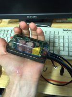
Compact Field Oriented Controller, ASI + Grin, limited run

Bartimaeus said:
Just got one of these for work, looking at ways to control it using a microcontroller. The data sheet mentions a proprietary library for the serial protocol:

Communication to the drive is via a proprietary ASi object dictionary using the ModBus RTU protocol. At the physical layer, RS 485 protocol is standard with options of TTL 232, CAN OPEN or LIN.

Is this object dictionary available/ is there documentation somewhere for it?
When you download and install the BACDoor package, one of the files in the program folder is ASIObjectDictionary.xml, which is not fun to read but which does have all the commands in it. The BAC controller manual references a couple documents, BAC Object Dictionary and ASI ModBus Protocol, which I assume are proprietary but you could try contacting ASI and talking them into providing you with copies.
 
justin_le said:
Anyways, here are the exact hole locations and dimensional diagram as promised. The side holes are 90mm apart, while the four bottom holes are on a rectangle 80.5mm x 26.6mm

Hey, I know they are blind... but how deep do the bottom holes go? I am making my mount for it tonight based off your layout, and I just realized I dont know how much thread I should have coming out.
 
MrDude_1 said:
justin_le said:
Anyways, here are the exact hole locations and dimensional diagram as promised. The side holes are 90mm apart, while the four bottom holes are on a rectangle 80.5mm x 26.6mm

Hey, I know they are blind... but how deep do the bottom holes go? I am making my mount for it tonight based off your layout, and I just realized I dont know how much thread I should have coming out.


Just received mine! It looks so sick!

Anyway the threaded holes look to be 8.9mm deep. The threads don't go all the way down though.
 

Attachments

  • ImageUploadedByTapatalk1438291109.674925.jpg
    ImageUploadedByTapatalk1438291109.674925.jpg
    44.5 KB · Views: 4,322
Grizzl-E said:
MrDude_1 said:
justin_le said:
Anyways, here are the exact hole locations and dimensional diagram as promised. The side holes are 90mm apart, while the four bottom holes are on a rectangle 80.5mm x 26.6mm

Hey, I know they are blind... but how deep do the bottom holes go? I am making my mount for it tonight based off your layout, and I just realized I dont know how much thread I should have coming out.


Just received mine! It looks so sick!

Anyway the threaded holes look to be 8.9mm deep. The threads don't go all the way down though.

Looks awesome. Why has no one done this before?! Lol

Thanks for measuring I'll make it 8mm and use a washer if I have to use less.
 
Grizzl-E said:
Just received mine! It looks so sick!
Anyway the threaded holes look to be 8.9mm deep. The threads don't go all the way down though.

Hey great to see these units arriving in people's hands. Remember that the controller will be all but useless until it is tuned and configured to your particular motor. The more recent V1.5.3 version of the Bacdoor software is attached to this post here, and the directions for tuning are pretty much still the same as Robbie's earlier posts for the Bac500+ devices, only now you can set the voltage and phase current correspondingly higher:
http://endless-sphere.com/forums/viewtopic.php?p=978256#p978256

For people who ordered the larger BAC2000 units, you'll obviously need to prepare an appropriate cable harness that includes a pinout of either the TTL level or RS485 level communication leads. Here's an example of how we did a simple harness that has a throttle plug, a 6-pin CA plug (V2 and V3 compatible), and the TRS jack for communication with the standard CA programming cable.
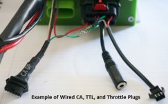
BAC2000 Signal Plugs.jpg

The phase and battery leads hook up with screw down terminals inside the housing cover. On the battery lead, we have a 1mOhm inline shunt resistor crimped to the cable, with the black, blue, and white CA-DP plug wires soldered to it. It's covered in shrinkwrap in the photo unfortunately. And you'll notice that there are some extra thinner gauge red wires on the V+ battery lead. One of these is for the Cycle Analyst V+, and the other is for the key switch input on the signal plug.

You must connect the Key-In line to the battery V+ voltage in order for the controller to power up, since that supplies power for all the logic and control circuitry.

View attachment 3
For the 16pin Molex Connector, the pinout from the datasheet is as follows:
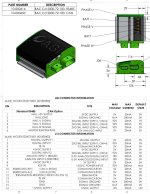
BAC2000 Pinouts.jpg

We've found that rather than using the pin7 Throttle Input, it's more convenient to hook up the throttle signal line to pin 6, the analog brake input. In the BACDoor setup utilty, you can then choose your throttle signal source to be the analog brake input line, and then again map this so that you have throttle signal from say 1.2-4.0V, and have regen mapped to start at 0.8V and go maximum at 0.0V, and then you'll have proportional accelleration and braking with a single wire. Of course if you have separate analog throttle and ebrake signals on your vehicle, then each should use the appropriate pin.
View attachment 2

Hope that's enough to get people started.
 

Attachments

  • BacDoorSetup_1_5_3_0.zip
    2.9 MB · Views: 127
justin_le said:
Hey great to see these units arriving in people's hands. Remember that the controller will be all but useless until it is tuned and configured to your particular motor.
Just a suggestion...Host a repository for user configurations so people can easily find a config for their specific motor and/or upload their own tweaked config so the best possible configurations for specific motors and uses will filter down through the community.

Or an output config option on your simulator would be pretty sweet...just sayin.
 
r3volved said:
justin_le said:
Hey great to see these units arriving in people's hands. Remember that the controller will be all but useless until it is tuned and configured to your particular motor.
Just a suggestion...Host a repository for user configurations so people can easily find a config for their specific motor and/or upload their own tweaked config so the best possible configurations for specific motors and uses will filter down through the community.

Or an output config option on your simulator would be pretty sweet...just sayin.

While initial values and constants could be shared, you would still need to go through the "learning" config to get the specific numbers for your setup.
 
Another suggestion, since you do not yet have premade harnesses for the bac2000, you should include in the options with the molex connectors; the wire connectors for the CA2,3 and the female programing connectors for the CA. I think most will be buying these anyway and this prevents the frustration of having to go hunt for them else where on the site.

http://www.ebikes.ca/shop/ebike-parts/ca-accessories/cables/ca-6pinf.html
and
http://www.ebikes.ca/shop/ebike-parts/ca-accessories/cables/ca-trs.html
and maybe also
http://www.ebikes.ca/shop/ebike-parts/connectors/conbag.html
 

I may have gone a little overboard on the heat sink.

Hey Justin, how much current do you think this little controller will take before the thermal gradient from the mosfets to the heat sink becomes so high that the thermal rollback doesn't have time to kick in and It turns into a silicone dioxide paperweight?

I may strap my little 5" pc to the handlebars this week so I can watch the internal temperature and see how long the thermistor takes to catch up.
 
Grizzl-E said:

I may have gone a little overboard on the heat sink.

Hey Justin, how much current do you think this little controller will take before the thermal gradient from the mosfets to the heat sink becomes so high that the thermal rollback doesn't have time to kick in and It turns into a silicone dioxide paperweight?

I may strap my little 5" pc to the handlebars this week so I can watch the internal temperature and see how long the thermistor takes to catch up.

I have the same question, but I have the feel he probably hasnt gotten the answer yet...
on a lighter note.. you call that a heatsink? I have a 5" aluminum block and a 20x14 fin attached to that. :lol:

My understanding is, thermal rollback is conservative, and will not let it burn up... PLEASE correct me if im wrong. lol
 
I wonder if anyone has tried or considered cooling one of these with mineral oil? Like the gamer pc fad a few years back?
:idea: :mrgreen:
 
mjayt said:
I wonder if anyone has tried or considered cooling one of these with mineral oil? Like the gamer pc fad a few years back?
:idea: :mrgreen:
I did read about someone filling a cheep old school controller with mineral oil. I think it worked well. It was just hard to seal in. Do some searching and you might find it. One thing to point out is the newer sine wave controllers with FOC and all the fancy stuff are more efficient which means less heat. :)
The best way to tackle a heat problem is not to produce it in the first place. ;)
 
Arlo1 said:
mjayt said:
I wonder if anyone has tried or considered cooling one of these with mineral oil? Like the gamer pc fad a few years back?
:idea: :mrgreen:
I did read about someone filling a cheep old school controller with mineral oil. I think it worked well. It was just hard to seal in. Do some searching and you might find it. One thing to point out is the newer sine wave controllers with FOC and all the fancy stuff are more efficient which means less heat. :)
The best way to tackle a heat problem is not to produce it in the first place. ;)

and then crank the power back up until heat becomes the limiting factor again? :lol:
 
Grizzl-E said:

I may have gone a little overboard on the heat sink.

That's pretty decent looking I would say. The most important detail is that it is mounted to the vehicle in a location with fins exposed to good airflow. At the speeds I'm presuming you're travelling the passing wind will be a lot stronger than you get from the muffin fans usually blowing over heatsinks of this size.

Hey Justin, how much current do you think this little controller will take before the thermal gradient from the mosfets to the heat sink becomes so high that the thermal rollback doesn't have time to kick in and It turns into a silicone dioxide paperweight?

You can't program in a nominal max phase current beyond the 74A value (not quite 80A, I'll be correcting this documentation shortly) and at that current there is plenty of time margin for the thermistor to heat up fast enough for rollback to kick in before there is risk of controller mosfet damage. You'll notice too that there is an instantaneous phase overcurrent fault setting set to (IIRC) 120 amps, and if there is a drive anomaly resulting in a current spike through a mosfet this would shut things down abruptly. I haven't done thermal rollback tests on yet on the PhaseRunner enclosure, but on the earlier BAC500+ devices we'd see the rollback kick quite effectively once the heatsink was around 90oC, and at that heatsink temperature, the mosfets shouldn't really be in any danger. The only exception would be if one of the wasn't making proper thermal contact to the heat spreader for some reason due to an assembly mishap.

I may strap my little 5" pc to the handlebars this week so I can watch the internal temperature and see how long the thermistor takes to catch up.

Do post the results of this. I'm not sure when I'll get time to do the promised wind tunnel thermal dissipation tests so any data points here will be appreciated.
 
Do post the results of this. I'm not sure when I'll get time to do the promised wind tunnel thermal dissipation tests so any data points here will be appreciated.


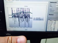
Sorry for the low tech method of posting but BacDoor occasionally locks up this little xp tablet. I couldn't get the internal temp up over 53C while trying to overheat it. I don't have a long hill or a trailer here to test with atm. I think I can safely say that the internal temp rises slow enough that at max programmable power levels the thermal rollback should have no trouble protecting this controller.

I'm sold on the FOC controllers. The power curve is just incredibly smooth, a fair bit more so than a standard sine wave controller. I may pick up a bac2000 model to try to give my mxus 4045 6t a little more power and move the 800 to a RC mid drive build. Is there any plans to carry larger models in the future?
 
Its awesome you did this, but I am having a hard time telling what dots are what on your graph.
How much amperage do you have it set for? Is that vehicle speed in mph or kph?
 
High purple dots are motor current. Middle green dots are temp. Low blue dots are speed.

I put my laptop in a backpack this morning and got some better data with field weakening at 100% to artificially load up the controller. And then ran out of battery juice. But is there any way to export the data besides a screenshot? Seems so primitive.

Fun fact, if you set the auto field weakening current to 200% for example you can hit the instantaneous phase current trip limit. 116 amps max set point in my controller. Makes sense but it makes me wonder if the max motor current limits, 93 amps max set point in my controller, are subject to the same percentage overrides.

ie will setting higher than 100% values on limits allow higher than set point power limits?

You can't program in a nominal max phase current beyond the 74A value

Exactly what is the set point name your referring to here? I'm having trouble finding it.
 
Grizzl-E said:
High purple dots are motor current. Middle green dots are temp. Low blue dots are speed.
thanks.. I think i get the idea.. on my work monitor I see 3 black and a green.. lol.

Just so I can get an idea of the wattage, what voltage are you running this at?
EDIT:
Nevermind.. I just saw your battery voltage on the screenshot.. its 69.7 something volts.... :mrgreen:
 
Grizzl-E said:
But is there any way to export the data besides a screenshot? Seems so primitive.
Ha, I'm not sure it qualifies as datalogging if the data are not, in fact, logged. :roll:

Under the Extensions tab, does Record Ongoing Network Traffic do anything useful? I imagine you'd have to write a script to interpret the output, so "useful" is relative...

You can't program in a nominal max phase current beyond the 74A value

Exactly what is the set point name your referring to here? I'm having trouble finding it.
Is this just "Rated motor current" under Peripheral Selection -> Motor Nameplate Ratings?
 
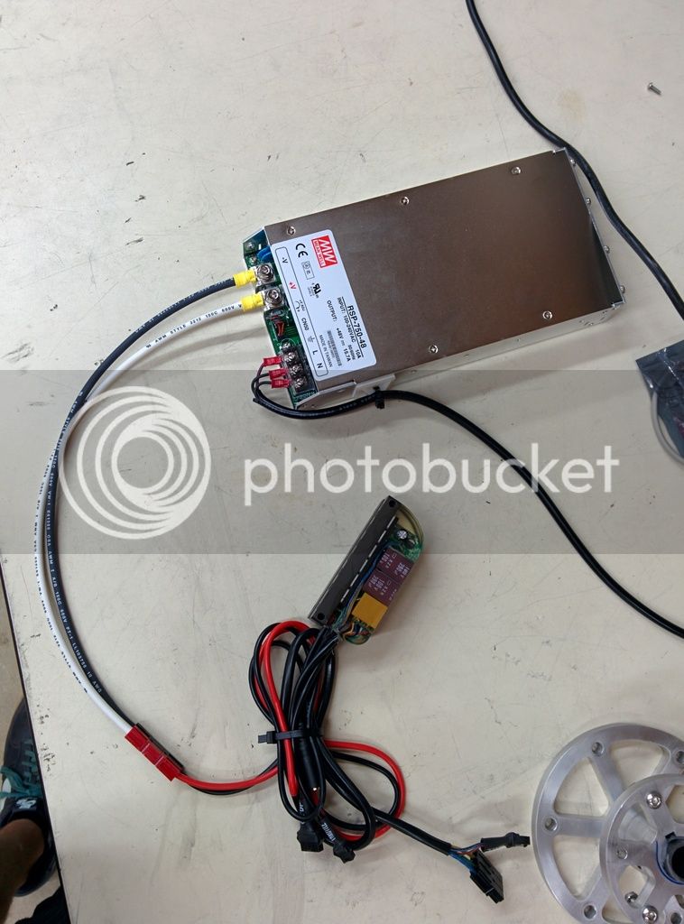
Got mine in yesterday and it looks great! My one concern is that it is displaying a different voltage on the DC bus in BacDoor than I see with a multimeter. Is there some sort of scaling factor I need to apply in BacDoor for this? I've been powering it with a mean well RSP-750 at 48V and the software is telling me I'm at 41V.

I can say that it is capable of spinning a motor up to at least 580Hz commutation frequency (no load). I'll hopefully get the chance to push it faster today :D.

The BacDoor interface is awesome and the quality of this controller is already obvious. I ran into a bit 9 and separately a bit 12 error (over current and over voltage) and getting back up and running was as simple as clicking reset. FOC is the future and I'm totally stoked these guys are building it.

 
toolbag said:
Got mine in yesterday and it looks great! My one concern is that it is displaying a different voltage on the DC bus in BacDoor than I see with a multimeter. Is there some sort of scaling factor I need to apply in BacDoor for this? I've been powering it with a mean well RSP-750 at 48V and the software is telling me I'm at 41V.
Same here. Multimeter says 48-49, PhaseRunner says 39.

Mine was in the mailbox when I got home last night and I didn't have as much time to work on it as I'd like, but with the wheel in the vise in my workshop, the configuration went very smoothly. Then I set everything up on the bike and after an hour of cable routing and zip-tying, I got no power and a flashing LED. By then it was dark in the driveway and I had a couple other things on the to-do list, so I left troubleshooting for tonight. Updates and photos when I've made some more progress.

In the meantime, does anyone have some insight on the battery voltage discrepancy?
 
tightbox said:
Has anyone tried this with an Astro Flight motor yet?

Yes. Anyone?
 
Back
Top