BMS Battery Alloy Shell Charger Problems

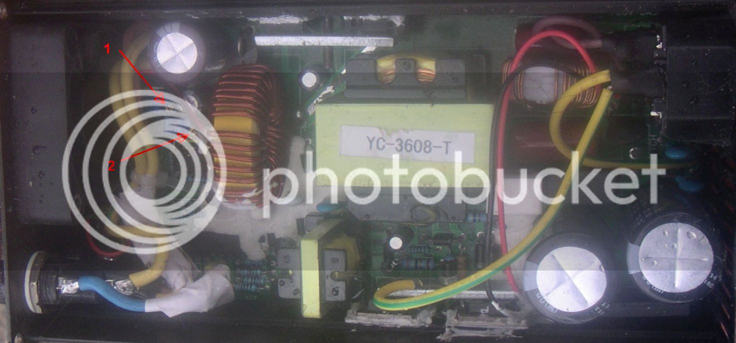
Ahh so now I see the identical circuitry around the hi and low side transistors. R20 is 2R20 (2.2 ohms) so R6 should be the same correct?
I'll get the bits from the local electrical store (thanks for offer) and solder in a couple of new leaded R's as you suggested. Thanks for the hole desoldering tip! I'll have to wait til Monday til the shop is open so no progress for a while.
I like learning about these things, anything but basic circuitry was a mystery to me ( even though I've a reasonable understanding of basic electrics) so it's good to start to understand how it all fits together
Cheers for your help
Kdog
 
yep, i think it would cost $2 to ship it to you. but it would be airmail so telling how long it would take.

anyway you can just use a regular 2.2ohm leaded resistor and solder that back into the circuit. you can follow the trace going from one side of that surface mount over to the base leg of the transistor.

the emitter of that loside transistor is connected to the negative terminal of the rectifier diode, and you can see the trace running along the edge of the pcb. the emitter is the far right leg of the transistor, the collector is the middle leg and the tab. that tab had high voltage so it needs to have clean contact on the surface of the insulator silicone sheet.

just thought of this. you can see how the emitter of the hiside transistor connects to the collector of the loside transistor in the oscillator circuit. the common name is push/pull but the arrangement of transistors one on top of the other between ground and the 340V is called "Totem Pole" circuit.
 
An aside- how much voltage adjustment is typically available on the bmsbattery alloy chargers? I've got an EMC-400 36V (43.8V 8A) one and was mainly wondering lower limit I might get, but it would be nice to know the upper too. I've taken a pic as there are a few versions and marked the 2 pots- is that course and fine adjustment?

PICT0003.jpg
 
dnmun said:
no, they have nothing to do with adjusting the output voltage. i recommend that people do not tamper with their charger if they do not know what it is they are doing or why.

That's quite a statement considering just how much building and modding goes on in this group- if it stopped how many posts would there be?

Can anyone (else) give please some constructive advice?
 
no, you should read what others have posted up already. if you don't know which one adjusts the output voltage by now it means you have not read anything yet. use google search if you don't wanna read what others have already posted.
 
OK, those two are current, one does the peak current so I assume the other is when it changes charge modes.

So shifting wires around there is a 3rd pot tucked away right in the corner under the mains in and fuse holder- that adjusts the Voltage (in case anyone else wants to know). It's well hidden so easily missed.
 
dnmun said:
no, you should read what others have posted up already. if you don't know which one adjusts the output voltage by now it means you have not read anything yet. use google search if you don't wanna read what others have already posted.

I had looked and didn't find the information I needed so thought I'd get a little help.
 
dnmun said:
there is a third trimpot close to the TL494 IC controller chip. see if you can find it and post up a picture.

as said a couple of posts ago I found a third pot right in the corner hiding under the mains in and the fuse wiring after trying the two I'd seen initially which adjusted current when tried so knew there must be another somewhere. I haven't tried adjusting it yet but I'm hoping that the range will extend down to act as a 12V charger. The charger is nominally 8A so I'll need to check if that stays the same when the voltage is lowered but I'll possibly lower it anyway because it's very close to the maximum charge rate for the battery.

 
An aside- what do you guys use to hold components in place to stop damage by vibration? I recently had a capacitor leg snap. I guess potting compound but those one use pack things seem an expensive answer for one component.
 
Thanks dnmun for your help last week
My parts arrived, in they went, and now I have a functioning charger again.
I've another charger to fix but it'll be for a later date
Thanks again
K
 
Hey guys, not sure if this is the right thread to post in since my charger isn't broken, but the level of knowledge here is astounding - way past what I need for such a noob question.

Long story short, I'm moving from 12s to 16s, and was hoping I could adjust the charger (EMC1000) up. Based on this thread and others, it looks like a matter of finding the right trim pot and adjusting. As many others have noted, though, the Andersons don't get power until a battery is hooked up presumably closing a relay.

Does this mean if I take off the cover, there will be a location before the relay that I can read the voltage off, or is it not that simple? I just need to know where i can read the output voltage without having to hook up a battery (which will alter the result anyway)

I've barely used this charger and it'd be a waste to just put it in storage and get a new one if I can't adjust it, so any help would be appreciated.
 
it has been a long time since i had one of them open but as i recall the EMC1000 is hard to reach the spot where the positive output goes to the relay. you have to take the end cover off and stick the probes in under stuff.

the output from the schottky diodes goes to the toroid so follow those traces from the toroid over to the relay and on the negative or ground side look for the traces that go to the shunt wire and past it.

the voltage trimpot is on the very end. i think there is a picture somewhere of which one it is.

the transformers are designed for specific voltage ranges so it may be hard to increase the voltage by 33%. i would expect the power output to increase 33% also because the current the oscillator pushes is fixed by a resistor attached to the source leg of the switching mosfet on the driving section. but i do not know that for certain. just assume it.
 
Thanks for the quick reply.

What inspired me was a thread on another forum that said they modified a EMC400 to do between 2v and 104v, using a combination of the "coarse" and "fine" trim pot. That said, I think the test was only done with a multimeter, and it was never attached to a battery, so it's possible that the 2v and the 104v was never a feasible voltage. That thread was old anyway. Like 2012. So maybe they've changed schematics since then.

I might pop it open this weekend anyway if I have time, and compare photos and see if mine looks a lot like the old one, or nothing like it. While it's open, I might take a photo - Would you mind helping me identify if the transformer would be within range?
 
Hello,

looking for diodes for EMC 2000 (36s) - ideally in EU. Any suggestions where i could buy it please?

Thanks,
Wojtek
 
Hello all. I am new to this forum and found this topic on Google. We ordered 12pcs 12.6V 3S - 10A C300 Chargers from ecitypower BMSbattery.com. We intended to use them to Charge our 50Ah Lithium packs for outdoor purpose. On arrival we unpacked one and plugged it to the AC power outlet 230VAC (no battery on the DC). The light came on briefly and then a short pop! Checking the fuse and it was burned. Replaced the fuse and connected it again to the wall 230VAC (no battery to DC) and nothing happend, no light, no current on the DC. So I thought bad luck, lets try the other twelve units. Now it gets really strange, all twelve units show the same problem and burn the fuse and after replacing it they don't show any sign at all, no light no current on DC just completely dead! We opened and checked the board and components but there is no visual sign of anything burned. One unit had a burned smell but also checking this one inside there was nothing to see. I am trying to get my money back. I have no confident in the products from BMS as you can understand. If one unit fail this can happen but all twelve? :?:
 
Have you got the polarity right?

The use a strange reverse connection sensing method, so that when there is no battery connected, it shows the reverse of the expected polarity. its strange and I killed a few fuses that way.
 
Back
Top