
You are using an out of date browser. It may not display this or other websites correctly.
You should upgrade or use an alternative browser.
You should upgrade or use an alternative browser.
HP ESP120 48V (51.4V) 57A 3KW Server Supply Thread
- Thread starter ZOMGVTEK
- Start date
JoeG
10 mW
- Joined
- Feb 4, 2009
- Messages
- 34
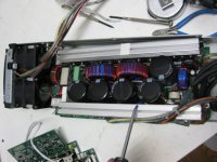
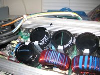
My limited ESP120 blew a Mosfet the other day! I was about 15 minutes into a charge and I while I was about 30 feet away in the garage, I heard a loud pop. When I went to investigate there was zero Amps output, no smoke or smell though. Got out the ohm meter and checked each supplies voltage. Found the stock supplies putting out 53V each, and the limited supply putting out zero volts. I pulled it apart and found a blown 20N60C3 Mosfet had blown. The Mosfet is right next to the output wires of the rear AC in board. I was using an opamp circuit to pulse the voltage up & down( see prior post for circuit)to limit current, and I guess the supply didn't like it  . It worked fine for about 12 hours of run time. Any thoughts out there as to how to prevent the supply from blowing/what went wrong?
Joe
. It worked fine for about 12 hours of run time. Any thoughts out there as to how to prevent the supply from blowing/what went wrong?Joe
Attachments
Artur
100 kW
- Joined
- Jul 3, 2014
- Messages
- 1,117
I need your advise. I have 2 ESP120.
Here is the first one, everything looks OK: [youtube]9Svu_saEbDM[/youtube]
And here is 2nd one, It was OK, multimeter showed me same voltage as on first one, then I tried to solder + and - wires, and next time I tried to turn it ON ,fans start spinning, after 4-5 seconds I hear *beep* (you can hear in video on 26th second), and multimeter shows 9v and goes to 0... maybe I connected some pins wrong? or I damaged it some how? have no idea whats happened.
[youtube]kBsgq-iGRIA[/youtube]
JoeG
10 mW
- Joined
- Feb 4, 2009
- Messages
- 34
Artur,
Sorry to hear that you are having trouble. One of my ESP-120's beeped once then shut down when I put 106V onto the pot pad by mistake. I removed power from the units right away. When I removed the faulty circuit, it restarted and ran with no problem. I would start by verifying all the connections are not shorting out to anything. Then compare ohm meter readings on the + & - DC out terminals on the 2 supplies that you have. If they are different, then you will have to open the case of the faulty unit to determine what came loose or bridged when you were soldering it. My daughter has my camera or I would post a picture of the DC out connection area on my blown supply. It completely detaches from the unit with about 8 screws, and a few connectors.
Hope this helps,
Joe
nedfunnell
10 mW
- Joined
- Jun 30, 2009
- Messages
- 32
It looks like these have a pretty great ability to adjust voltage if I am reading correctly- is it true that one can get as low as 24v by applying positive voltage to the solder pad of the removed trim pot? How low can the voltage be set with the stock trim pot? Does the adjustment voltage need to come from some external source, or can I use a different pot off of the output? Does it need isolation or ground bonding? I want to use this at 48v in conjunction with another 42v power supply (a Sony APS-162) to get 90v for my 22s setup. Does this sound feasible to everyone?
Hey JoeG
what is the part number for the diodes you are using? I've been searching for 60+A schottkky diodes and all I get are huge bolt like diodes or three pin double diodes max rated at 30a per side.
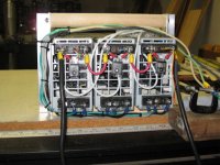
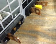
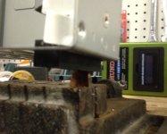
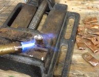
By the way I copied your approach of using ring terminals but instead of cutting strips, I used 1/4" copper pipe, cut 1" lenghts, flattened one side with a vise, then I filled the other unflattened side with plumbing wire by heating the piece with a torch, once it was liquified I just stick the PSU straight in to it, this way I was able to grab both terminals. here is a picture if any one likes to try it, took me like 10 min total per psu.
what is the part number for the diodes you are using? I've been searching for 60+A schottkky diodes and all I get are huge bolt like diodes or three pin double diodes max rated at 30a per side.
By the way I copied your approach of using ring terminals but instead of cutting strips, I used 1/4" copper pipe, cut 1" lenghts, flattened one side with a vise, then I filled the other unflattened side with plumbing wire by heating the piece with a torch, once it was liquified I just stick the PSU straight in to it, this way I was able to grab both terminals. here is a picture if any one likes to try it, took me like 10 min total per psu.
Attachments
hi,
For people looking for lower voltage. I removed the voltage adjustment pot. I soldered 3 wire to the pads and passed them thru the back of the case. Then, soldered a 250K (likely a 50k would work) pot to the wires after screwing everything back together. I put the pot wiper to the back center pad (the one closest to the bottom). I get 41.9 - 53 Volts by adjusting the pot. It seems very stable but I haven't put a load to it yet.
Hopes that helps someone.
nedfunnell
10 mW
- Joined
- Jun 30, 2009
- Messages
- 32
I am having the same trouble as Kin and Artur- my ESP-120 does not give DC output. It did when I first tested it, no problem. However, after I soldered some wires onto the output terminals, I get nothing. Just 3mV. I followed JoeG's advice to remove the output board and inspect for any heat damage or bridging- none seen. Without the 3-pin bridge, I get a blinking green status LED. With it installed, a get a solid orange warning LED. Anyone know what the fix is for this? I am trying to get my bike ready for the Vetter Challenge on Sunday, and time is short.
liveforphysics
100 TW
nedfunnell said:I am having the same trouble as Kin and Artur- my ESP-120 does not give DC output. It did when I first tested it, no problem. However, after I soldered some wires onto the output terminals, I get nothing. Just 3mV. I followed JoeG's advice to remove the output board and inspect for any heat damage or bridging- none seen. Without the 3-pin bridge, I get a blinking green status LED. With it installed, a get a solid orange warning LED. Anyone know what the fix is for this? I am trying to get my bike ready for the Vetter Challenge on Sunday, and time is short.
Perhaps contact Brandon of DigiNow about borrowing a supercharger for the Vetter challenge?
nedfunnell
10 mW
- Joined
- Jun 30, 2009
- Messages
- 32
liveforphysics said:nedfunnell said:I am having the same trouble as Kin and Artur- my ESP-120 does not give DC output. It did when I first tested it, no problem. However, after I soldered some wires onto the output terminals, I get nothing. Just 3mV. I followed JoeG's advice to remove the output board and inspect for any heat damage or bridging- none seen. Without the 3-pin bridge, I get a blinking green status LED. With it installed, a get a solid orange warning LED. Anyone know what the fix is for this? I am trying to get my bike ready for the Vetter Challenge on Sunday, and time is short.
Perhaps contact Brandon of DigiNow about borrowing a supercharger for the Vetter challenge?
That would be super neat, but I am not a competitor. I will only be doing the first half of the course. My bike has no aeromods and is 5.5kWh, so I can't finish the whole course with the pack. I have been enjoying seeing what the supercharger can do for Benswing, though!
nedfunnell
10 mW
- Joined
- Jun 30, 2009
- Messages
- 32
OK, I have a theory as to why mine won't work:
The power supply is rated for 200-240v AC input voltage. It's probably expected to be used in 208v applications most of the time. When I measured just now (late at night), the input voltage I am giving it is 248v. Perhaps it is shutting down output due to overvoltage? When I tested it before, it was the middle of the day and perhaps the power company's transformer (in my neighbor's yard) was more loaded and the voltage was lower, and it worked. I don't have a way to reduce this voltage (except maybe turning on the oven and dryer?) so I am not sure how to test this. Thoughts?
The power supply is rated for 200-240v AC input voltage. It's probably expected to be used in 208v applications most of the time. When I measured just now (late at night), the input voltage I am giving it is 248v. Perhaps it is shutting down output due to overvoltage? When I tested it before, it was the middle of the day and perhaps the power company's transformer (in my neighbor's yard) was more loaded and the voltage was lower, and it worked. I don't have a way to reduce this voltage (except maybe turning on the oven and dryer?) so I am not sure how to test this. Thoughts?
nedfunnell
10 mW
- Joined
- Jun 30, 2009
- Messages
- 32
nedfunnell said:OK, I have a theory as to why mine won't work:
The power supply is rated for 200-240v AC input voltage. It's probably expected to be used in 208v applications most of the time. When I measured just now (late at night), the input voltage I am giving it is 248v. Perhaps it is shutting down output due to overvoltage? When I tested it before, it was the middle of the day and perhaps the power company's transformer (in my neighbor's yard) was more loaded and the voltage was lower, and it worked. I don't have a way to reduce this voltage (except maybe turning on the oven and dryer?) so I am not sure how to test this. Thoughts?
Well, with the help of three long, skinny extension cords and an alternate 240v load, I got the input voltage down to 238v, and observed no change in the situation. Nuts. Any new ideas?
Edit: Did an Rshunt adjustment on my normal charger, got it making 2.6kW. This drew the source down to 226v, and still the ESP-120 will not come to life.
I have been using two ESP-120's as my car charger for aaages now and they are AMAZING!
I was prompted by a PM to dig into what I did, so I have posted my code etc. on Github and will improve with images and actual documentation when time permits.
I was very lucky to get the upper and lower power/data connectors...
Hope this is of use to someone. Welcome some code cleanup/additional features etc.
https://github.com/spmp/LiFePO4-Charge-Controller
plasmaticosine
10 µW
- Joined
- Sep 11, 2015
- Messages
- 5
Thank's for posting SpmP!
I have 6 of these supplies, and want to charge 84s lipo 25ah pack to 350V! To charge a retrofitted prius to improve gas milage, of course.
My supply seems to shut off at 56V when I apply less than -0.2V (gets overvoltage fault). If I am not able to bump the voltages I will need to get another supply (dont want to), but it seems like Spmp was able to as well as the guys on the German site. When I find the solution I will post details.
plasmaticosine
10 µW
- Joined
- Sep 11, 2015
- Messages
- 5
Woot! Emailing the Germans with google translate works great! :lol:
Hallo Kalen,
der Widerstand ist auszutauschen ( unteseite vom Sekundärnetzteil ).
Gruß
Christian
Hello Kalen,
the resistance has to be replaced (unteseite from secondary power supply).
greeting
Christian
When I get home in a few days I will try this and post if it worked or not!!
Hallo Kalen,
der Widerstand ist auszutauschen ( unteseite vom Sekundärnetzteil ).
Gruß
Christian
Hello Kalen,
the resistance has to be replaced (unteseite from secondary power supply).
greeting
Christian
When I get home in a few days I will try this and post if it worked or not!!
Attachments
nedfunnell
10 mW
- Joined
- Jun 30, 2009
- Messages
- 32
Glad to see some new activity on these units. Still nobody has ideas about the problem of the supplies simply failing to come on after attaching output cables? A few people have had this issue.
izeman
1 GW
Unterseite = bottom/lower side, in case you need that. There was a typo, so maybe that's why google couldn't translate it.plasmaticosine said:unteseite
plasmaticosine
10 µW
- Joined
- Sep 11, 2015
- Messages
- 5
Good success today!
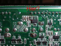
I replaced the bottom resistor in the picture above in my previous post so I can push the voltage to 63V. I pushed up to 62.5V, and left it running for 20 minutes and nothing got very hot.
I did not have a 2.7k resistor so I soldered 2x1.3k resistors in series, and made a little arch above the 0603 pad

I took some readings, while adjusting the pot 100mV each time. The results are pretty great - very linear curve of potentiometer voltage vs output voltage. An R^2 of 0.9994!!!!

After scanning the range of the output, I got one of those spools of plastic coated steel wire (used for gardening) in a bucket of water as a loadbank. I only ran a 12A load for 5 minutes before the plastic started to make smoke bubbles... the wire was wound too close together and could not be cooled with the water!
Also I'm in an apartment so I can't get easy access to 230Vac (I would have to pull out the oven) so I used my homebrew re-wound microwave oven transformer for testing purposes.

My next step is to have a larger load (45A?) and run the power supply at 62V for many hours... I want to make sure the power supply does not explode/overheat. I'll probably borrow a Flir camera for this test. Not many charging stations can supply that amount of kW so it's overkill, but I like testing in more extreme conditions then it will see in use.
Nice Idea! I'd be game for contributing to a wiki page although I'm not sure how to make one. There is a wiki page which links to this thread lol.
https://endless-sphere.com/w/index.php/Chargers_LiIon_Bulk_Chargers_HP_Server
I replaced the bottom resistor in the picture above in my previous post so I can push the voltage to 63V. I pushed up to 62.5V, and left it running for 20 minutes and nothing got very hot.
I did not have a 2.7k resistor so I soldered 2x1.3k resistors in series, and made a little arch above the 0603 pad
I took some readings, while adjusting the pot 100mV each time. The results are pretty great - very linear curve of potentiometer voltage vs output voltage. An R^2 of 0.9994!!!!
After scanning the range of the output, I got one of those spools of plastic coated steel wire (used for gardening) in a bucket of water as a loadbank. I only ran a 12A load for 5 minutes before the plastic started to make smoke bubbles... the wire was wound too close together and could not be cooled with the water!
Also I'm in an apartment so I can't get easy access to 230Vac (I would have to pull out the oven) so I used my homebrew re-wound microwave oven transformer for testing purposes.
My next step is to have a larger load (45A?) and run the power supply at 62V for many hours... I want to make sure the power supply does not explode/overheat. I'll probably borrow a Flir camera for this test. Not many charging stations can supply that amount of kW so it's overkill, but I like testing in more extreme conditions then it will see in use.
SpmP said:I think we need a wiki page for these beasties, or are they a bit of a _has-been_ thing?
Nice Idea! I'd be game for contributing to a wiki page although I'm not sure how to make one. There is a wiki page which links to this thread lol.
https://endless-sphere.com/w/index.php/Chargers_LiIon_Bulk_Chargers_HP_Server
Attachments
This is bordering on Necromancy...
But after many years of reliable service, my ESP-120 based charger has undergone major overhauls due to a number of factors, like the people I bought my batteries off giving me the wrong charging parameters to maintain warranty, two ESP-120's dying due to salt air corrosion, etc. etc. So the circuit board I lovingly hand printed is an absolute dogs breakfast having been hacked and modded to keep up with progress.
But the code is good, or the idea is good, yet I want to re-do this completely, but have not the time and energy to do it again all by myself.
I am looking for peeps to help do V2 of this charger.
I have an idea of how I think it should be done. I want to do it with an ESP32 module such as NodeMCU-32s and to integrate my cell top module master board with the charger so I can track the maximum cell voltage etc.
I need help with
[*] Schematic concepts - there are quite a few things I am rusty on now
[*] CAD/PCB Layout - Ideally I will do this in KiCad to keep it open, so also component/module design
[*] Code - Instead of rolling my own drivers I am switching to Arduino for ESP32
[*] Interface - Currently using a serial console and I2C OLED, I want to switch to serial console and Android app via bluetooth or TCP etc.
I will update my github repo with pictures some time in the next few months as well/
I suspect this will take a while 8)
It would also be great to get more testers of the cell top modules.
Any takers?
nedfunnell
10 mW
- Joined
- Jun 30, 2009
- Messages
- 32
I am not qualified to help with any of that, but I lend you my moral support! I am excited to see more activity on this thread. Still hoping my curiously-dead/not-dead ESP120 can be made useful again.
liveforphysics
100 TW
I recently gave away the 6 of them that I had or I would be a tester for you. I'm glad you've got them figured out, and I'm shocked more Zero owners are jumping on running them as home fast charging stations (just because they are a little heavy and bulky to carry for only 3kW).
Similar threads
- Replies
- 3
- Views
- 2,494
- Replies
- 12
- Views
- 11,248
- Replies
- 44
- Views
- 13,688
- Replies
- 62
- Views
- 8,883