Open Source Arduino transmitter/receiver for (V)ESC

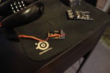
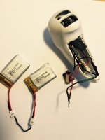
I got some PCBs from Jacob a week ago and yesterday I spent all day soldering, debugging and testing:
IMG_4835.JPG


I had to make a patch for the regulator to work:
IMG_4831.JPG


A CP2102 PCB makes a built in programmer:
IMG_4834.JPG


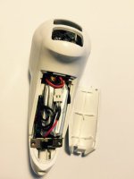
USB Port for programming and charging:
IMG_4838.JPG

IMG_4839.JPG


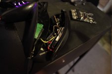
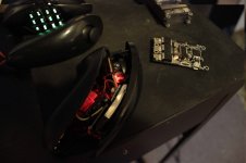
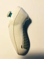
Here ts is next to the nyko kama:
20150816_231748.jpg


I went for a 6km ride yesterday and it worked perfectly. I have tested the nyko kama with my early version of the PCB for months now and it has been super reliable, so this one should also work well.

The features of this nunchuk are:
* The connection is solid and reliable.
* Built in rechargeable lipo battery and built in charger
* USB port for charging/uploading firmware/configuration/debugging
* Standby time: over 100 days on a full charge
* Usage time: almost 2 days on a full charge (about a month if the longboard is used 1 - 2 hours every day)
* Lighter and smaller than the nyko kama
* Charge time: 1 - 2 hours

Much of the time I spent yesterday was on testing the power consumption in low power mode and how the charger works, which was much better than I expected. First I thought a power switch would be needed, but that does not seem to be the case unless you intend to leave it without charging the battery for more than 100 days.

I will help Jacob with updating the design a bit with the following:
* Connect the regulator correctly
* Remove some resistors that aren't needed
* Change the joystick footprint and position to make it fit better
* Add a CP2102 USB-to-UART chip to the PCB so that the programmer is build in. This will allow a twice as large lipo battery which doubles the standby time and usage time.
* Add something to make the MCU able to measure the battery voltage.
 
Hi Vedder, I love the controller design and hardware and would like to try it out. Is there already a repo with hardware/PCB and BOM, or do you/Jacob plan on selling assembled parts soon?

Nordel said:
:?: I thought I would first have to upload something from link in the Readme. :?:
This comment doesn't make sense to me. Can you please share an updated readme that makes sense to you?
Well, the nRF24L01+ is very reliable, especially when you use the PA, LNA version. I haven't read your link, but it uses the default Nunchuck bluetooth communication? Some people tell it is unreliable.
I found the nRF24L01+ reliable enough, this one: http://www.amazon.com/Arrela%C2%AE-NRF24L01-Wireless-Transceiver-Compatible/dp/B00KKR148A/ref=sr_1_1?s=pc&ie=UTF8&qid=1439841898&sr=1-1&keywords=nrf24l01%2B+pa

This is the nRF24L01+ with PA and LNA antenna:
http://www.amazon.com/Studio-Bazaar-wireless-module-NRF24L01/dp/B012AH8DDQ/ref=sr_1_cc_1?s=aps&ie=UTF8&qid=1439841878&sr=1-1-catcorr&keywords=nrf24l01%2B+pa

Cheers,
Erwin
 
erwincoumans said:
Hi Vedder, I love the controller design and hardware and would like to try it out. Is there already a repo with hardware/PCB and BOM, or do you/Jacob plan on selling assembled parts soon?

Thanks :)

I will upload the design to github when I have tested it and I think Jacob will make sure that controllers can be bought as kits or maybe even assembled.

Here is what I did today after work:
kicad_1.png

NunchukRF_V3_3d_front.png

NunchukRF_V3_3d_back.png


Schematic:
http://home.vedder.se/public/pictures/Nunchuk_Jacob/V5/NunchukRF_V3.pdf

I have added the cp2102, moved everything around to place the connectors so that it is easy to solder cables to them and moved the joystick a bit. The regulator connections are also fixed. A USB connector can be soldered directly to the pads for charging, programming and communicating.

One feature I might work on is to make a wireless connection from BLDC Tool to the VESC using the USB connector on the nunchuk :)
 
That's so cool!...

Its great to see some progression with this.

Its also great when people in two parts of the world can work together to create some awesome stuff.....
 
I have a box on my kitchen table with 100 nunchuck shells ready for a kit, it will come with a 300mah lipo and the new PCB that Vedder helped me with, but this all needs to be confirmed, if ppl want just nunchuck shells from me then they can do that also, and yes the PCB will be put on GitHub.
 
Hi,

I want to jump in the discussion. The controler you developed is realy smart and fits perfectly to your VESC BLDC which I use now for some time and I must say that it a perfect esc! But I want also keep the discussion upright that started on this thread from erwincoumans about the arduino based controller. The Idea is relay smart for me because I get a lot experience with the arduino and want to jump on this project. I know about the remaining ressources of the VESC, but I'm far away to understand the code with its underlying ChibiOS/RT. So it would be great to get a open, well documented interface towards the VESC over the UART to realize a control Arduino based for those (like me) who have ideas that can be easily realized on an arduino platform (or lets say easier for non professional coders). I want to catch up the project from erwincoumans and support him if he wants to.

From my side, I defined the following requirements:

  • - Biderectional communication over NRF24L01 secured by a checksum and predefined fixed MAC address
  • - Configurable: PWM or serial communication to ESC (for VESC or other ESC)
  • [- Predefined PINs for 2812 LED, free usable output (for a horn?) and additional inputs for e.g. stand sensors/list]
    • - Usability of all features of the VESC like PID control etc.
    • - feedback for board voltage etc. over LED. In a next step maybe also the usage of a OLED

    Especialy for the communication to the VESC I hope of the support of Vedder to offer a documented UART message interface.

    Nice would be:
    Message based and documented protocoll with cheecksum
    Upstream:
    • UART based application like the nunchuck with PID etc.
    • UART based current control with break

    Downstream:
    • Input voltage
    • ERPM
    • current
    • 'Cosumed current [mAH]
    • Wh in/out


Within the Arduino I think it would be nice to implement also Smoother from wiiceiver and other features. Post your ideas if you want.

Vedder, maybe we can come together in a skype session to discuss a possible UART protocoll for the communication? I can send you my contact over PN or Email if it is OK for you.

Regards

Andy
 
erwincoumans said:
Nordel said:
:?: I thought I would first have to upload something from link in the Readme. :?:
This comment doesn't make sense to me. Can you please share an updated readme that makes sense to you?
I'm unable!

Next questions:
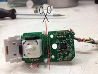
IMG_0303 - Kopie.JPG
I can cut the PCB at the red line (with the beautifull scissor on top)?

Code:
Transmitter has a potentiometer pin on Analog 3
-a is potentiometer pin that i connect to Analog 3 on Arduino?
-b is just +?
-c is gnd?

Do I need 2s Lipo to run my transmitter, or would it run on 1s to? Would be nice, cause i have a nice small 1s usb charger.
 
Yes, you cut at that line.

Usually the outer pins are ground and VCC (5V) and the center pin is variable. In my case, the ground was 'c' in your picture. If you have a multi-meter you could try out measuring the pins, just attach ground and 5V and measure the voltage on center pin and ground and move the potentiometer. Note that there are 2 potentiometers on that know, for X and Y axis. I only used up/down axis, not left/right.
 
RollingGecko said:
Within the Arduino I think it would be nice to implement also Smoother from wiiceiver and other features. Post your ideas if you want.

Vedder, maybe we can come together in a skype session to discuss a possible UART protocoll for the communication? I can send you my contact over PN or Email if it is OK for you.

Yes, it would be great to have an example of an Arduino communicating with the VESC over UART protocol. The large amount of examples, information and number of users of the Arduino eco-system is valuable. On the other hand, I like to learn more about VESC and ChibiOS, so both ChibiOS+STM32F4 and Arduino are useful to explore.
 
I love how we both went with very similar ideas when making our transmitters (I haven't seen this thread yet)

rec.jpg
trs1.jpg
trs2.jpg

Definitely following this!
 
If any one needs wifi cases or joysticks for the wii I have them,
We could look at changing to the stm32f103 chip and you could run Arduino code,

Aslo I'm been talking to Austin creator of the wiiceiver and he has agreed to help make an Arduino receiver for the PCB that we have been working on so it is plug and play, basically we need to get the spi data from our PCB and get the wiiceiver to read it.
So if any one here wants to help with that it would be great.
 
erwincoumans said:
Usually the outer pins are ground and VCC (5V) and the center pin is variable. In my case, the ground was 'c' in your picture. If you have a multi-meter you could try out measuring the pins, just attach ground and 5V and measure the voltage on center pin and ground and move the potentiometer. Note that there are 2 potentiometers on that know, for X and Y axis. I only used up/down axis, not left/right.
I don't have a multi-meter. It's from an original Nintendo Nunchuck someone know's what I have to connect?


Nordel said:
Do I need 2s Lipo to run my transmitter, or would it run on 1s to? Would be nice, cause i have a nice small 1s usb charger.
 
Arduinos let me freak out!IMG_0332.JPG
Didn't touch them for some days and now the 2nd one seems to be broken-.- Chinese crap... I think i will order 2 new ones with original ftdi chips, hope this will solve one of my problems with that remote control.
This isn't fun anymore:(
 
Tombombadil1988 said:
@erwincoumans Can you tell me how long the battery lasts on your Arduino transmitter side? Have you implemented sleep commands to save some battery?

I haven't measured, but using the Arduino Nano + nRF24L01+ I would guess over 10 hours without power management, but I didn't measure it yet. I use an on-off switch and turn it off when not using it. This is using 2 tiny LIPO batteries of 3.7-4.2Volt each (1300mAH total).

There is also the Picoino Cell Arduino that you can plug an nRF24L01+ in, without soldering. It is even more power efficient. It is slightly too big due to the radio module sticking out on the wrong side. If it would be rotate 180 degrees, it might fit the Wii Nunchuck.
See pictures at http://www.amazon.com/Atmega328p-au-Microcontroller-Compatible-Transceiver-Modification/dp/B00WFM2N60
 
Tombombadil1988 said:
I don't mind the soldering so much, but I wouldn't like to damage the nunchuck for the switch. Do you maybe have a picture of the switch to see how you fit it in there?

Sure, here are the pictures. This was just a quick prototype and it won't win any beauty contest. The switch sticks out a little bit and I made a small space under the lid. If you prefer, you can cut off the sides of such switch, and then you don't need to modify the outer shell of the Nunchuck (Kama in my case). Note that the switch is not rigidly attached to the case, it is just sandwiched between lid and case. Also I had to cut away several small parts inside the Nunchuck Kama to make space for Arduino and batteries:

FullSizeRender-7.jpg
FullSizeRender-5.jpg
FullSizeRender-6.jpg
 
Tombombadil1988 said:
Thanks for sharing Erwin! I thought that the wireless nunchuks had a way to turn them on and off with an integrated switch or something.

Yes, mine did as well, but the button was attached to the part of the original PCB that I had to cut away to make space for the Arduino...
 
RollingGecko said:
@ Nordei: What happend in detail?
I hit my Arduino, then I bleed a bit. :shock:

But seriously, after I received them I did:
-connect them to win7 PC and tried a few hours to get them work... without success
-connect them to Linux PC... now it worked, both arduinos light up when connectet to usb, but only one was detected by my PC (I upload the ''Blink'' sketch, and it worked). I assume the other one has a broke CH340 chip from what i read, told that to my Amazon seller and he will send me a new one.
-NOW a few days later I wanted to upload the Tx sketch but when I plug in my Arduino it Blinks random, some times nothings happens when I connect it. Looks to me like a loose connection.

Off Topic
Could I just connect my Nunchuck to my VESC with wires, just to check it out and do some settings while I'm working on Arduino Tx/Rx?
 
I have ordered a Nyko Kama nunchuck to use with my dual VESC setup for my dual drive board when it arrives, what additional parts do I need to buy and what is currently the easiest method of wiring and programming it to work with VESC?
 
@Moja Reeves, that's described in the first post of this thread.

Today I powered my Arduino from an old PC psu while connected to my PC, he let out a bit of smoke and began to stink. I immediately disconnected everything. I feared the worst, but lol now it's working-.-

@erwincoumans
sry about my stupid question on the readme, everything is fine I'm just a noob (....a little less now)
 
Back
Top