cycborg
1 kW
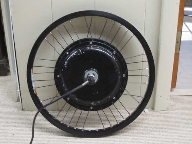
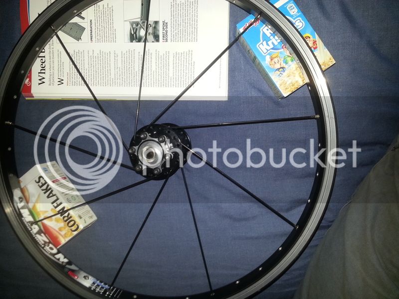
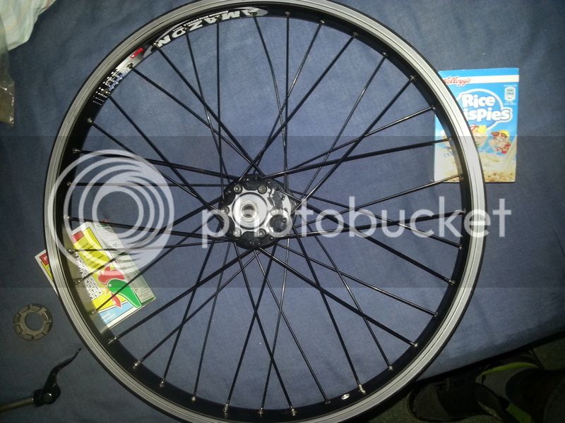
The hub appears to match the “NineCont front” dimensions from the Grin calculator - the spoke circle diameter is 233 mm. As for the rim, 406 is actually the bead diameter; ERD is 394 mm according to this chart (PDF).NeilP said:Out of interest did you calculate accurate lengths from spoke angles for each different spoke length or just use 'generic' near enough figures.
...
What 9C motor is it? what is the spoke hole circle diameter and spoke hole diameter.
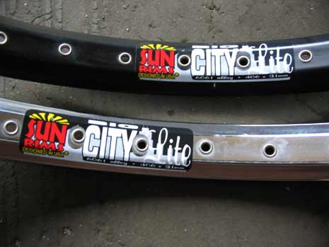
I have the ERD of the rim as 406mm
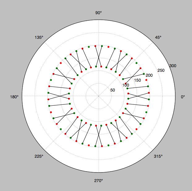
From these numbers, for the first pattern I calculate these lengths and their corresponding angles from normal to the rim:
80.6 1.8
81.1 5.4
83.8 12.2
For the second pattern, there’s a 4th spoke length and angle for the “V” spokes:
82.2 8.9
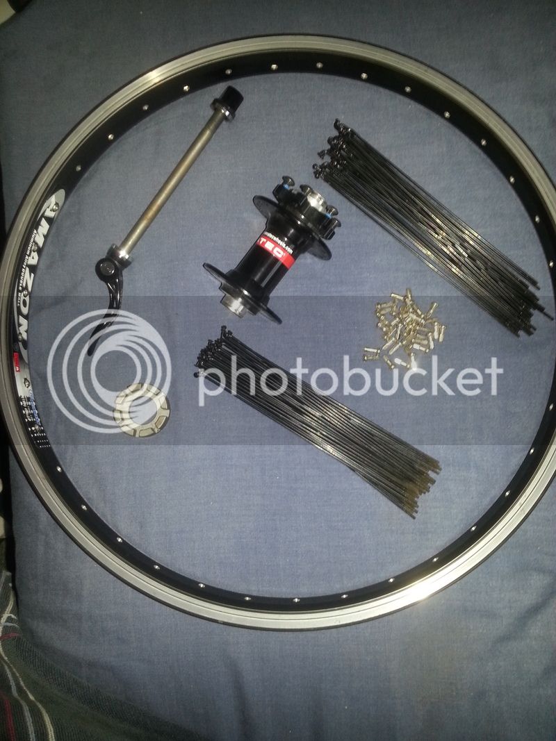
I ordered 82 for the two shorter lengths and 85 for the two longer lengths.
Your idea of crossing the most parallel spokes in these patterns looks good - basically it changes the shortest length and angle to the longest. (80.6 mm, 1.8 deg -> 83.8 mm, 12.2 deg)
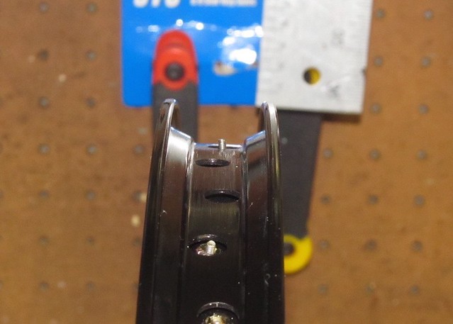
I was avoiding something like this because of the offset spoke holes, but the offset looks minimal so it’s probably not an issue: