Ultra power dense charger project.

Arlo1 said:
peters said:
liveforphysics said:
Ripple current isn't a bad thing to the batteries. Think of them as massive filter capacitors.
Ok, I see. And there is the max. charge current recommendation in the battery datasheet. The peak or the average (or RMS) current should be limited to it?
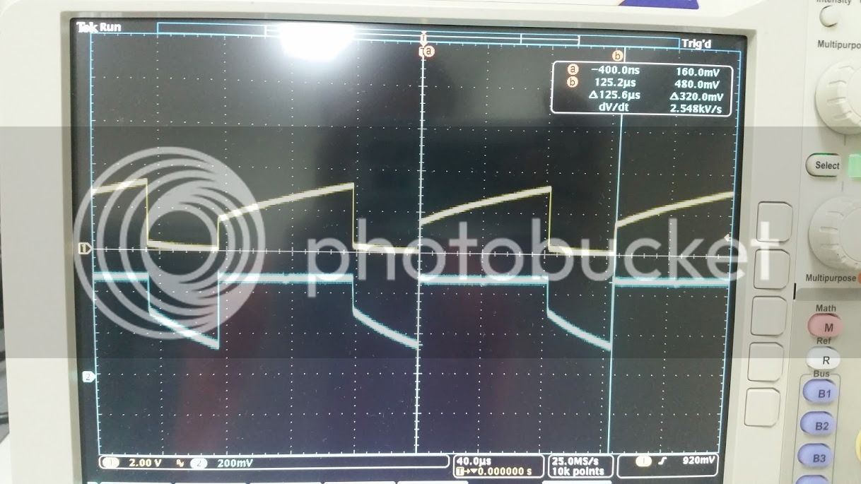
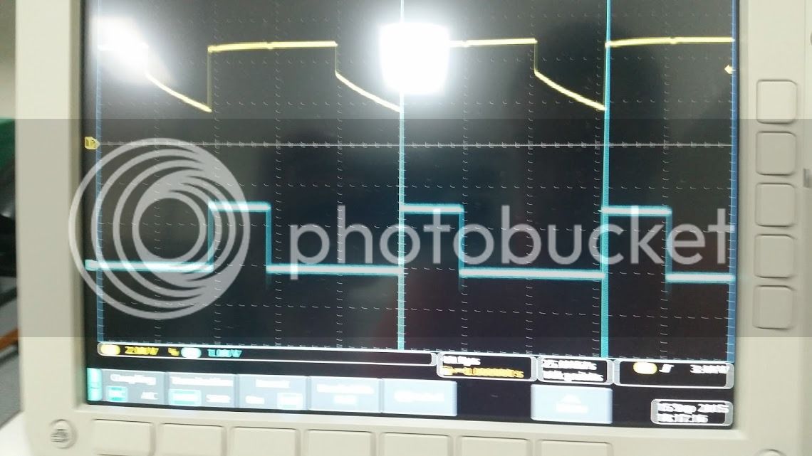
If the average is set to the max then the pulses at the PWM frequency are above the recommended charge current (can be multiple of that with a low voltage-high current power supply), can't it generate some unwanted reaction inside the battery?
Older 2013&2014 zero stuff is 1c charge rate and less with a cold battery. Not sure about 2015 or any of the other cells they have used.

Yeah, but the question is if the charge current is PWM then the peak should be limited to 1C or the average (then the peak is more, sometimes even 2C..3C)?
 
The cells filter it into an average, over even huge amounts of ripple.

I just ordered this cart of parts for trying out this device.

http://www.digikey.com/short/tzdpqj
 
I have always wondered if you modeled the battery properly as a RC circuit could you charge it faster by tuning the charger for maximum power transfer? Meaning you need ripple for maximum power transfer, But the ripple frequency has to be tuned

----
Based on the test analysis of the characteristics of a lithium-ion power battery, an obvious polarization can be observed. The polarization characteristic could be simulated by the Thevenin model to some extent, however, the difference between concentration polarization and electrochemical polarization leads to an inaccurate simulation in the moments at the end of charge or discharge. An improved circuit model is presented in Figure 5, which is defined as dual polarization (DP) model, to refine the description of polarization characteristics and simulate the concentration polarization and the electrochemical polarization separately.

The DP model the composed of three parts: (1) Open-circuit voltage Uoc; (2) Internal resistances such as the ohmic resistance Ro and the polarization resistances, which include Rpa to represent the effective resistance characterizing electrochemical polarization and Rpc to represent the effective resistance characterizing concentration polarization; (3) the effective capacitances like Cpa and Cpc, which are used to characterize the transient response during transfer of power to/from the battery and to describe the electrochemical polarization and the concentration polarization separately. Upa and Upc are the voltages across Cpa and Cpc respectively. Ipa and Ipc are the outflow currents of Cpa and Cpc respectively. The electrical behavior of the circuit can be expressed by Equation (6):

http://www.mdpi.com/1996-1073/4/4/582/pdf
 
Looks like the charger bits should show up on friday, excited to throw this all on protoboard!
 
Subscribed!
 
Woot! Today was a good day for progress. I got the timer circuit hooked up and running, and the chip is outputting an exploratory gate drive signal. Tomorrow Ill screw around with the feedback pin in an open-loop configuration to see how the gate drive changes. Then ill close the loop, and screw with it by hooking an RC filtered voltage divider to the gate drive, and putting the output on the feedback loop input to simulate what feedback a real FET and inductor would be giving.

Here is a shot of the timer circuit up and running (PWM will be 8khz for a nice slow starting point):

timers_zpsbhodo0gp.jpg


Here is a shot of the gate drive signal as referenced to the timer circuit (Gate drive is actually 15V, just indicated as 1.5V on a 10X probe)
Gate_zpsetjyx3va.jpg
 
My two bobs worth. Please DONT re-do the 10KW EMW charger. Its a pretty poor design. Microcontrollers are good supervisors, but poor SMPS controllers.

This (inverted buck) topology was what I used in my original 2Kw charger design (which ate mosfets due to the poorly sized inductor saturating and becoming a power resistor instead) - and another (working version) is available online - http://ludens.cl/Electron/latsup/latsup.html. I scaled this one out to 2.5Kw. Took one big bugger of an inductor to avoid saturation.

Current mode is the simplest way to do this, and keeping below 50% duty cycle eliminates the need for loop compensation.

Inductors - Toroid, or massive bar inductors. EE-core need to be ridiculously sized (that 70mm one, even double-stacked, is going to need quite an airgap (3-5mm) to avoid saturation, and then you need to take into account the localised heating of the windings over the gap due to flux concentration) Bar inductors are the easiest to wind, although they are not a closed magnetic path, interference is very likely (as is a gapped EE).

If you want to know the maths behind this - N87 saturates at 0.350T, but you really shouldn't go over 0.3T in practice.

Flux density in an inductor is determined by the following:

B = (AL * N * I) /Ae

Where B is flux in mT
AL is in nH per turn squared
N is the number of turns
I is the current in amps
Ae is the effective area in mm2

Run some numbers through that and you will be surprised at just how large the flux density is in some scenarios.

I needed a 1.5mH inductor capable of 20A before saturation. I tried a 2mm gapped ETD59 (pretty big core) - a 2mm Gapped ETD59 N87 core has an AL of 311nh.
This equates to 70 turns of wire.

Running these numbers against my 2mm gapped ETD59 core

B = (311 * 70 * 16) / 368
B = 946mT - 0.95T (!!!!) Obviously undersized!

Rummaging around in my junk box - I found a massive bar core (25mm*50mm*100mm), with 25 turns of litz wire around it, measuring at 90uH. This works out to 0.144uh/turn squared. The core itself weighs 350g, and makes an ETD59 look like a toy.

Plugging the numbers in, need 83 turns to get 1000uh (1mh - needed for 20A, may as well go big).

B = (144 X 83 X 20) / 1250
B = 191mt = 0.191T - Plenty of headroom.

Running this coil at 30A (not going to happen but anyways)

B = (144 X 83 X 30) /1250
B = 286mT = 0.286T - yep still possible.

Its very interesting how large a core you need for a buck inductor due to its DC content - what would be fine for a half/full bridge is useless for high powered buck or flyback.

In energy storage topology (as you figured) lower frequencies mean larger inductors. But they also mean you can get away with poor routing, not need to use copper foil or litz wire to reduce skin affect, and the input filters for common mode noise reduction are far simpler to model. It also means you can use things like IGBT's with much better SOAR ratios than mosfets of the same capabilities.

If you want maximum energy out of your powerpoint - you need good power factor. I would be looking at buck PFC topology. Its a single inductor, single switch topology using a controller UCC29910A.

I've designed some big buck SMPS'es before - the maths is reasonably straightforward.
 
Yeah, my power supply mentor here has also stated that the arduino is great for oversight, but not control.

Ideally this design will switch much faster than 8 khz, that is just a starting spot. Ideally i am hoping to switch at 20 or even 30khz, but i will take what I can get.

As far as maximum energy goes, I am ok with losing a few hundred watts of absolute output to avoid the complexity of a pfc stage at this point.

I have an amazing mentor here that has made 40kv Xray power supplies, who seems to know his stuff big time, and he will be helping me out with optimizing the layout for high freq operation. I like the high voltage transistor for voltage feedback, that seems clean. What is the temperature stability on that?
 
The feedback is a current mirror basically. Its pretty stable. Beats the snot out of using TL431's and optocouplers (which also require loop compensation).

The same feedback mechanism is used in the UCC29910A reference design as well - that's where I originally stole it from :)

The ludens design isn't mine, its actually something someone else designed years before I designed my version, and a very strange co-incidence - proof that no matter how clever and original you think your design is, someone else has already though of it!
 
What kind of parts cost estimate would you say one of these chargers would run? Debating whether to wait and try building one or purchase an off the shelf charger.
 
Nuts&Volts said:
What kind of parts cost estimate would you say one of these chargers would run? Debating whether to wait and try building one or purchase an off the shelf charger.

The total parts cost should be somewhere in the 50-100 dollar range depending on what current you are after (mosfet and inductor size)
 
Woot! I successfully charged a battery today! a single 18650 at .8A. Then, disaster struck when changing the shunt value to make it flow 2A


The fet turnoff makes a spike on the clock pin, sadly I do not have a scope shot of the spike on 2A, but you can see clearly see it on the .8A test.


That spike is causing the clock to trip high, which causes the gate drive to go high and give the fet a double-turn on event:


I am assuming my dodgy protoboard is giving my this headache, so ill be attempting to design up and etch a real one here shortly
 
Sweet! The pricing for the parts is very enticing. Glad to see you work through design/test. I just started creating a parts cart on Mouser to get an idea of cost. Also trying to read as much as I can on Buck converter circuits.

I'm aiming for a 5-6kW charger with this topology. Wish I could off more assistance, but I will be following your progress closely.
 
Design it with Kicad and use osh park its cheep and very good quality.
 
I have few questions.

Why do you not use a filter capacitor on the output of the rectifier? This gives you a higher usable voltage when you only have 110Vac (ie I have a 117Vdc pack) and would the smoother voltage not make life easier on the boost circuit.

Along the same line, I understand that the ripple current on the output isn't too big of an issue, but what about the output voltage ripple? Is targeting 3V reasonable. Any insight is appreciated.

Additionally I understand that the driver does the current limiting, but what tells the charger to stop when you reach full voltage? It looks like SW1 is used to start the charger, do you plan to also control it to stop the charger?

Can you recommend a power supply to use with this circuit? I want to add it to my mouser parts list.


-Kyle
 
Regarding pulsed battery charging:
-Faster Charging time
-Higher eff
-Lower Cell temperature (!!!)

http://120.107.180.177/1832/9901/099-1-17p.pdf
 
Might be a dumb question, I am told to understand that all power circuits plugging into mains utility have to meet some standards so that they dont interfere with them.
1. Is that true?
2. what ways can power circuits break utility mains?
3. How are we tackling this in this project.

I am building my first E Bike, and am trying to make the charger.
 
crank2giri said:
Might be a dumb question, I am told to understand that all power circuits plugging into mains utility have to meet some standards so that they dont interfere with them.
1. Is that true?
2. what ways can power circuits break utility mains?
3. How are we tackling this in this project.

I am building my first E Bike, and am trying to make the charger.

If this is your first experience with electronics and E-bikes. DO NOT try to build a charger. There are indeed a host of issues with this type of charger but none of which, if executed properly would prevent it from being a viable charger. A full UL/CSA certified product is another story.
 
I made some good progress! I got my boards back from OSHpark, and proceeded to do a solid 25A sustained with two burly fans into a zero cellbox. Thats 2.5KW output for a critter the size of a paperback :D

LFP ordered some more fets for experimentation, So we will see what all happens here soon.

(Ignore the rough SMD soldering, I accidently bought the 0402 book, and had to bodge them on to 0805 pads)


Sick! Looks awesome. 2.5kw damn...

What's the input/output voltage for that? (sorry if I missed it somewhere) 220 in, ~120 out?

Thanks,
-Troy
 
grindz145 said:
Sick! Looks awesome. 2.5kw damn...

What's the input/output voltage for that? (sorry if I missed it somewhere) 220 in, ~120 out?

Thanks,
-Troy

Right now it is just a current limiting buck, as I have not implemented the voltage feedback loop. That being said, the main drive fet and diode are SiC parts, and rated for 1200V, so if you traded the cap to something that could handle that, then theoretically you could go to ludicrous voltage.

I have tested this one from 5 to 600VDC in, and have tested the output on a single cell,and a 28s zero module. It is very stable except for a very small area where Vin is really close to Vout, it hisses and the pwm duty cycle goes a little nuts, but i have left in that state for several minutes, and the parts stay cool...
 
Farfle said:
Right now it is just a current limiting buck...

I have tested this one from 5 to 600VDC in and have tested the output on a single cell,and a 28s zero module....


Super Exciting. Even now I'm sure you can just disable charge when Vout = VFullCharge - Vripple

2.5kw... :)
 
h0tr0d said:
Regarding pulsed battery charging:
-Faster Charging time
-Higher eff
-Lower Cell temperature (!!!)

http://120.107.180.177/1832/9901/099-1-17p.pdf

Woah! And they studied a Sanyo 18650 also. Note that the optimum ripple frequency which corresponded to the lowest AC impedance was about 1 kHz.
 
Farfle said:
grindz145 said:
Sick! Looks awesome. 2.5kw damn...

What's the input/output voltage for that? (sorry if I missed it somewhere) 220 in, ~120 out?

Thanks,
-Troy

Right now it is just a current limiting buck, as I have not implemented the voltage feedback loop. That being said, the main drive fet and diode are SiC parts, and rated for 1200V, so if you traded the cap to something that could handle that, then theoretically you could go to ludicrous voltage.

I have tested this one from 5 to 600VDC in, and have tested the output on a single cell,and a 28s zero module. It is very stable except for a very small area where Vin is really close to Vout, it hisses and the pwm duty cycle goes a little nuts, but i have left in that state for several minutes, and the parts stay cool...

Do you have the most recent version of your schematic?

As Vin approaches Vout you approach a very low duty cycle - have you checked to see if this is pulse skipping behaviour? I remember some queer behaviour with some current mode controllers when the current feedback went below zero. Have a look and see if your current feedback is doing something weird here.

At 2.5Kw - I bet that inductor was getting hot! Have you done your saturation calculations? Due to the large DC component in buck mode saturation is a major PITA. To hit 2.5Kw on mine at 50Khz I needed a much larger inductor than originally anticipated. When they saturate they stop being inductors and start being resistors. I'll see if I can find your core material and run some calculations for you.

Also - some fun and games await (and will blow out your costings) for your input capacitors at these current levels - over half my budget was in those caps! You need really low ESR, or go a PFC frontend (also not fun). Best power factor I managed to get was 0.7 IIRC.
 
Nice work. Do you have an updated schematic or anything? I ordered parts to put one together but haven't really gotten past that point yet.

Great progress
 
Back
Top