
Yep. Covered in the Guide.Scotty T said:I'm guessing that the ebrake and throttle connectors on the Grinfineon are are not used because throttle and brakes will connect to the CA.
You are using an out of date browser. It may not display this or other websites correctly.
You should upgrade or use an alternative browser.
You should upgrade or use an alternative browser.
Cycle Analyst V3 preview and first beta release
- Thread starter justin_le
- Start date
NeilP
1 GW
don't be tight with the crimper. just buy your own. and don't buy that second one from Amazon, it is more expensive and on ly does one part of the crimp at a time. the CA one is a proper tool , with a laminated set of jaws that does the whole crimp in one...and it is cheaper. This is why Justin started to sell the crimpers he does, because the cost of the Pro style crimpers was astronomical, usually running in to 90 -100 USD or more. He got a supply of the same style and is knocking them out for $29

look at the advertising image from the amazon site ..and the quality of crimps that more expensive Amazon one produces. If I did a crimp like that I'd cut it off and start again!
http://www.amazon.com/Engineer-PA-09-Micro-Connector-Crimpers/dp/B002AVVO7K
look at the advertising image from the amazon site ..and the quality of crimps that more expensive Amazon one produces. If I did a crimp like that I'd cut it off and start again!
http://www.amazon.com/Engineer-PA-09-Micro-Connector-Crimpers/dp/B002AVVO7K
jc-teklektik said:Configuration of negative deg/V scaling coefficients (Temp->TScale) for linear type sensors will be supported in the next release (3.0p11) - to be released in the near future.teklektik said:...to include the feature - and if so, will we target 3.0 or 3.1.jc.maquet said:Is it a chance that new release will support linear NTC in future ?
Will advise.
I'm sorry to report that this feature will not be available in 3.0p11 or the formal 3.0 release.
Considerations with providing Setup Utility support for this change have resulted in postponing the feature until a subsequent release (probably 3.1 beta 1).
Apologies for leading you astray on this matter, but sometimes stuff happens...

NeilP
1 GW
I think the download includes a readme text file.
It explains all.
It explains all.
The next release is 'soon' -- measured in weeks not months.
In any case, you should advance to p10 - it only takes a couple of minutes and should have been done early in your installation process.
Operating with old releases is not recommended.
In any case, you should advance to p10 - it only takes a couple of minutes and should have been done early in your installation process.
Operating with old releases is not recommended.
NeilP
1 GW
The update is so quick, just update now, then do again when next is out.
Even if Justin or tek said a new one was out in 2 days time, but I was not current, I'd still update today,
Even if Justin or tek said a new one was out in 2 days time, but I was not current, I'd still update today,
izeman
1 GW
you're in no hurry aren't you?NeilP said:don't be tight with the crimper. just buy your own. and don't buy that second one from Amazon, it is more expensive and on ly does one part of the crimp at a time.
seems you haven't used it yourself. all my crimps are top notch and i've done some hundred at least. this is a top quality crimper and a 100% 5* rating proves that all other ppl who bought it think the same.look at the advertising image from the amazon site ..and the quality of crimps that more expensive Amazon one produces. If I did a crimp like that I'd cut it off and start again!
so maybe justin's crimper is cheaper and may produce nice crimps but the one i suggested has it's advantages as well especially if working space is limited.
NeilP
1 GW
Each to their own, I'd rather use a dedicated tool, one size for one job tool specifically for those JST crimps,
If you prefer the more universal 'one tool does many' style crimper, then I won't knock you for it.
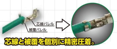
I prefer the ratchet style laminated head crimper, you can insert the terminal, partially close to hold it in place, insert the wire then squeeze. It crimps the wire section to one trnsion and the insulation to a different size all in one.
I just find the dedicated one easier than the universal, I have maybe 6 or 7 different tools, all capable of crimping the JST's and the yellow one from Justin has become my preferefd tool.
I had always too, bought the iniversal style, because the proper tools were always mega bucks, till Justin bought a load and started selling them
At least now he has the choice for himself.
If you prefer the more universal 'one tool does many' style crimper, then I won't knock you for it.
I prefer the ratchet style laminated head crimper, you can insert the terminal, partially close to hold it in place, insert the wire then squeeze. It crimps the wire section to one trnsion and the insulation to a different size all in one.
I just find the dedicated one easier than the universal, I have maybe 6 or 7 different tools, all capable of crimping the JST's and the yellow one from Justin has become my preferefd tool.
I had always too, bought the iniversal style, because the proper tools were always mega bucks, till Justin bought a load and started selling them
At least now he has the choice for himself.
r3volved
100 kW
I've had real bad luck with adding JST to hall wires. I think maybe the wires out of the motor are too thin or something...I had no problems putting connectors on controller side, but on motor side my crimps end up snipping the wire as I crimp. In the past I've just gotten sick of trying to use connectors on halls and i just keep soldering them right together instead.
Any advice on better crimping without cutting wires?
I'm using the JST tool and connectors from ebikes.ca
Any advice on better crimping without cutting wires?
I'm using the JST tool and connectors from ebikes.ca
NeilP
1 GW
sounds like brittle wire. maybe you are stripping with the cutter set too deep?
or is your wire too thick for the JST's ?
If you have crimped other JST's with no issues but only have issues with the hall wiring , then it rather points to the hall wire type.
For my halls I have always used the Xlye 5 pin ' mini XLR' ...or at least that is what they seem to have become called..
or is your wire too thick for the JST's ?
If you have crimped other JST's with no issues but only have issues with the hall wiring , then it rather points to the hall wire type.
For my halls I have always used the Xlye 5 pin ' mini XLR' ...or at least that is what they seem to have become called..
r3volved
100 kW
Seems like the hall wires out of the motor are like 1-2 strands of copper and the end of the crimp just cuts through. I'm going to try again with my new controller and see if I have better success.
I guess I could also make a connection harness with new wire and solder to the motor halls...I didn't even think of that until now...
I guess I could also make a connection harness with new wire and solder to the motor halls...I didn't even think of that until now...
teklektik said:How to Refresh Corrupted EEPROM Settings
Repair of corrupted EEPROM (CalOverwrite) can be achieved using the CA3 Setup Utility.
(Formerly, this was accomplished using the older separate Firmware Update Utility by means of a 'dual flash' technique. This new method described here is preferred.)
Until Grin Tech web site directions are posted, here's a temporary procedure to correct corrupted EEPROM using the newer utility:
Done!
- Download and install the latest CA3 Setup Utility from the Grin V3 web page.
- Hook up the USB cable and launch the utility.
- If a settings file was saved prior to the corruption incident, load it into the Setup Utility, otherwise skip this step and use the defaults.
The Setup Utility initially loads the data\default.hex setup file which contains factory defaults for all parameters in EEPROM:
- those that can manipulated with the normal V3 console buttons,
- hidden parameters only manipulable with the utility, and
- a number of device-specific calibration values set at the factory.
These factory calibration values typically vary from the specific device-specific values by a few percent and give the best accuracy. However, replacing them with generic defaults will have minimal impact. Ideally, if a settings file from the same device has been saved prior to the corruption incident, then it may be used in lieu of the default file to restore the unit to the original factory calibration.- Normally the Battery and Calibration Categories will not show the factory calibration parameters ('Show Protected Settings' is unchecked).
View attachment 1
Use the menu to 'Show Protected Settings' - new shaded parameters will appear with checkboxes.
View attachment 3
- Enable 'modification and write' of all shaded parameters by enabling the checkboxes.
View attachment 2
- Make any desired setup modifications.
- Write the complete suite of parameters to the V3.
I'm experiencing an odd issue with a V3 CA-DP that I can't find any info on anywhere else. The voltage is reading about 1.1V too low on a 14S battery. I've tried multiple batteries and controllers, and even tried plugging the CA into a CA-SA adapter with grin's molded shunt, and it's always the same - voltage too low. Would the fix above work for this? And what would I edit, the voltage scale? If the 'stock' number is 31.18 V/V, then should I do the math (52/50.9*31.18=32.04) to get the new number of 32.04 to put in there?
mlt34 said:I'm experiencing an odd issue with a V3 CA-DP ... The voltage is reading about 1.1V too low on a 14S battery.
...
Would the fix above work for this? And what would I edit, the voltage scale?
If the 'stock' number is 31.18 V/V, then should I do the math (52/50.9*31.18=32.04) to get the new number of 32.04 to put in there?
Yes, that procedure will work as far as accessing the protected values is concerned, but the part about flashing with generic values (and losing your per-device settings) is unnecessary and not a good approach in this case.Grin Tech V3 page said:VScale: This is used to calibrate the voltage display. The factory calibration is about 31V/V.
- Instead, use an existing settings file or just read the settings from your CA. Then enable the protected settings, make the VScale mod, then write them back to the CA.
- Or just use the Console buttons where Cal->VScale is readily available for direct edit.
In general:
- ( ( Calibration Voltage from DMM ) / ( Displayed CA Voltage ) ) * ( old Cal->VScale ) = ( new Cal->VScale )
Also, be sure to read the calibration voltage at the CA-DP connector to ensure the DMM sees the same voltage as the CA. If this differs materially from the battery voltage then something else is awry...
ColinB
100 W
Hi,
I have a CA V3 and a 2-3 year old Grin Infineon controller. Can I connect things to have e-brakes, cruise control, and regen braking? Presently I have the throttle going to the CAV3, and the brake to the Infineon. Applying the brakes cuts the motor, but does NOT cancel auto cruise!
Also, I think I have a wiring issue. The bike now drops out of cruise control fairly regularly. It's been working fine for a few thousand kms. The manual says cruise is cancelled on throttle application or ebrake input. (If ebrake is plugged into the CA.) What else could cause the cruise to drop out?
- The connections to my battery BMS may be suspect. I am not sure how to test that. I think this is the most likely culprit... but I'm not sure why. A few thousand K ago, when the pack was fully charged I un-plugged the bms wires, and when I reconnected it they didn't all light up right away. I un-plugged and replugged a few times, and it seemed ok. Dirty connections? Breaking wires? Not sure.
- The throttle is about 6 months old, with about 3000km use. Voltage readout seems smooth still. I don't think that is the problem, but possible? I wonder what would happen if the throttle was unplugged while cruise control is engaged?
Thanks for any thoughts.
Colin
Yes you can. Present behavior is as expected for the way it is wired.ColinB said:Can I connect things to have e-brakes, cruise control, and regen braking?
Presently I have the throttle going to the CAV3, and the brake to the Infineon. Applying the brakes cuts the motor, but does NOT cancel auto cruise!
From the Unofficial Guide, section "5.4 Auto-Cruise Control":
Please review these sections of the Guide for details on proper ebrake wiring:Unofficial Guide said:IMPORTANT: Do not use the auto-cruise feature unless ebrakes are installed and wired to the Cycle Analyst EBK input. Using auto-cruise with the conventional ebrakes connection to the controller will not disengage auto-cruise when brakes are applied and may cause a potentially dangerous runaway situation as soon as the brakes are released.
- "3.4 Important Conflicts with Controller Features"
- "5.3 eBrakes"
Your throttle stop has been mashed back requiring re-adjustment of the CA.ColinB said:The bike now drops out of cruise control fairly regularly. It's been working fine for a few thousand kms. The manual says cruise is cancelled on throttle application or ebrake input. (If ebrake is plugged into the CA.) What else could cause the cruise to drop out?
From the Guide, section "5.4 Auto-Cruise Control":
Unofficial Guide said:3. Auto-Cruise Dropouts: Sporadic dropouts in auto-cruise operation may be traced to a ThI->MinInput voltage offset that is too small. See ' 4.7 Test Throttle and Limit Settings (Interpreting Limit Flags)'.
ColinB
100 W
Thanks for the reply. I'll have to re-read the guide again. Plug the brake into the CA and the controller - why didn't I notice or consider that before? Sheesh.
Update: I re-read the guide, and poked through the settings. I've obviously forgotten everything that I've ever known about my CA, because the words on the page were not making much sense. I'll give it another go when I'm not so tired.
Contact cleaner question. How can I safely clean the multi pin contacts for the bms, that are "live." I don't want to short out my battery! I can't find if the things like "MG Chemicals Super Contact Cleaner" are safe for this type of thing. I suspect that will fix my cruise control dropping out issue, because re-seating all the connectors helped for one 20km ride. I'll re-check the throttle calibration also.
Thanks,
Colin
Motobikewheels
100 W
I need some help guys
On my buddies bike we changed the throttle, redid some wiring and the cycle analyst wouldn't turn on, the screen just flickered. So we checked the wires and put power back to it and it started smoking WTF
So i had a v3 board here that had a broken screen. Swapped out the boards and found that the hall sensor in the throttle is shorted between 5v and ground so i disconnected the 5v line before i powered it on the first time after replacing the board
Now the screen just flickers and thats it
I have done a bunch of custom wiring on these and would like to think i know what im doing :lol:
My main here is what is even needed for it to boot up power and ground? or do the shunt wires play a part in it?
On my buddies bike we changed the throttle, redid some wiring and the cycle analyst wouldn't turn on, the screen just flickered. So we checked the wires and put power back to it and it started smoking WTF
So i had a v3 board here that had a broken screen. Swapped out the boards and found that the hall sensor in the throttle is shorted between 5v and ground so i disconnected the 5v line before i powered it on the first time after replacing the board
Now the screen just flickers and thats it
I have done a bunch of custom wiring on these and would like to think i know what im doing :lol:
My main
izeman
1 GW
only power and gnd. nothing else is needed to boot it.
izeman said:only power and gnd. nothing else is needed to boot it.
That's correct. Normally putting a momentary short on the 5V throttle rail would cause the CA power rail to trip and the CA to reset itself without much consequence. But if was sustained for a length of time then it's possible that the small p-channel mosfet that controls the 5V bus going to the throttle output, LCD screen etc. was fried. When you apply power right now to the CA, do what voltage do you see between pins 1 (5V) and 2 (gnd) of the throttle plug? If there's no voltage here, then check between pins 1 (10V) and 2 (Gnd) of 5 pin PAS plug. If you DO see about 9-10V on the PAS plug power, then the linear regular is fine and you've likely just damaged the 5 p-channel fet that switches the 5V rail. If the don't see voltage on the PAS plug either, then the issue is likely further downstream on the linear regulator.
-Justin
Motobikewheels
100 W
justin_le said:izeman said:only power and gnd. nothing else is needed to boot it.
That's correct. Normally putting a momentary short on the 5V throttle rail would cause the CA power rail to trip and the CA to reset itself without much consequence. But if was sustained for a length of time then it's possible that the small p-channel mosfet that controls the 5V bus going to the throttle output, LCD screen etc. was fried. When you apply power right now to the CA, do what voltage do you see between pins 1 (5V) and 2 (gnd) of the throttle plug? If there's no voltage here, then check between pins 1 (10V) and 2 (Gnd) of 5 pin PAS plug. If you DO see about 9-10V on the PAS plug power, then the linear regular is fine and you've likely just damaged the 5 p-channel fet that switches the 5V rail. If the don't see voltage on the PAS plug either, then the issue is likely further downstream on the linear regulator.
-Justin
Thanks for the response
Not sure if you missed the part where i changed the board out to one that i know for sure works.
With just power and ground hooked up the display backlight comes on and flickers a bit. I just checked and there isn't any power on the 5v ...I do have power on the 10v
With this new board i have not once had the 5v hooked up btw
roadrash said:Not sure if you missed the part where i changed the board out to one that i know for sure works.
With just power and ground hooked up the display backlight comes on and flickers a bit. I just checked and there isn't any power on the 5v ...I do have power on the 10v
With this new board i have not once had the 5v hooked up btw
Ah sorry I didn't quite catch that the board was changed. What voltage are you attempting to power it up with? And is the backlight flickering in a rythmic / periodic manner or does it seem pretty random? I
Next thing to check if you do have 10V on the PAS plug is to open the CA and measure the 5V that is present between Gnd and 5V on the 5-pin programming header pads, right under the main microchip.
Motobikewheels
100 W
Holy crap now i did it
When i was checking for the 5v i on the lcd header i slipped and shorted something out.. Now its completely dead
I had 12v on the led + pad and thats as far as i got.. I know its not the ones you said to check but i was getting there . Figured while i was out there i would check a few other things.
Anyway here is the area i shorted out
When i was checking for the 5v i on the lcd header i slipped and shorted something out.. Now its completely dead
I had 12v on the led + pad and thats as far as i got.. I know its not the ones you said to check but i was getting there
Anyway here is the area i shorted out
Similar threads
- Replies
- 3
- Views
- 407
- Replies
- 0
- Views
- 275
- Question
- Replies
- 5
- Views
- 264
- Replies
- 2
- Views
- 580
- Replies
- 9
- Views
- 1,977