Nohassel motor drive project

Miles

100 TW
Joined
Mar 16, 2007
Messages
11,031
Location
London UK
An interesting open-design project.

Two independently controlled motors, coupled by an epicyclic
differential - this gives the advantages of a CVT and allows both
freewheeling and regeneration, all within a single unit.

There have been a few posts about this, here on E.S.
Per has now set up a Google group for the project, which has a lot more information:
http://groups.google.com/group/nohassel?hl=en
 
Cool.

That deserves a piccie:
 

Attachments

  • Exterior+-+ray+traced.jpg
    Exterior+-+ray+traced.jpg
    22.8 KB · Views: 8,196
Hi,

When I saw the title I was hoping the Nohassel drive was something like ship your bike collect to Miles and three weeks later it will be returned with Motor/Drive/Controller/Batteries installed. :D
 
If, like me, when confronted with this sort of thing you want to be able to visualize how it works, you might find this page helpful:
http://www.ecrostech.com/prius/original/Understanding/PowerSplitDevice.htm
It's mentioned in one of the Hassle files, but rather buried in there. It helps to understand how an epicyclic gear works and how it can be used as a CVT. I still am not fully clear how the magnetic/winding bits are activated, so if you can illuminate that for me I'd be grateful. :oops: :roll:

Edit:
This diagram helps a bit:
Nohassel-sectioned-logical+colours.jpg
also from the Hassle site.
 
This won't help with the electrics, but is a nice bit of interactive flash work on the PSD:

http://eahart.com/prius/psd/

Click on the link to move the sliders and see the effects...
 

Attachments

  • PSD1.jpg
    PSD1.jpg
    23.9 KB · Views: 8,053
Thanks, TD. What a superb bit of work!
If 1 picture = 1000 words, then
1 animation = 1000 pictures, perhaps.
 
Ya mon, since there are drawings of the NhM, a similar set of animations could be made. A bit beyond my current skill levels, but it could be fun to try...
 
I think this is correct... by changing the speeds of one/other/both motors, constantly variable output via the planets (green) is achieved.
 

Attachments

  • NhM1.jpg
    NhM1.jpg
    72.6 KB · Views: 8,033
You've just done what I was going to ask for next: labeled that image. Great. Now there was some reference to there being patents involved with some of this stuff. Perhaps those are Toyota patents. I wonder if Toyota could be either
a) make those patents "open-source" for 2 wheel vehicles OR
b) be persuaded to develop the motor for 2 wheel vehicles?
You can always dream! :wink:
 
This scooter claims to use ECVT but I can't find out what they mean by that:
http://gulfcoastveloteq.com/ebike_commuter_rsv.htm
 
paultrafalgar said:
This scooter claims to use ECVT but I can't find out what they mean by that:
http://gulfcoastveloteq.com/ebike_commuter_rsv.htm
I don't think they have anything other than a geared hubmotor: http://veloteq.com/veloteqgallery.com/comparison_chart1.htm
 
paultrafalgar said:
You've just done what I was going to ask for next: labeled that image. Great. Now there was some reference to there being patents involved with some of this stuff. Perhaps those are Toyota patents. I wonder if Toyota could be either
a) make those patents "open-source" for 2 wheel vehicles OR
b) be persuaded to develop the motor for 2 wheel vehicles?
You can always dream! :wink:

There's nothing particularly new about using differential gearing as a power split device. Military Tank track drive transmissions have been doing this since WWII. I've also seen power splits used extensively with mechanical/hydraulic CVT's. With mechanical CVTs the power split is most often used to increase the range of speeds available. While hydraulic CVTs use a power split to sacrifice speed range in exchange for higher efficiency and power.

I do wonder how this twin motor + planetary is any better than a single motor and planetary of the same weight. I just don't see any advantage that would justify the added complexity. Especially if a single motor system is able to use field weakening to extend it's rpm range.

Marty
 
lawsonuw said:
I do wonder how this twin motor + planetary is any better than a single motor and planetary of the same weight. I just don't see any advantage that would justify the added complexity. Especially if a single motor system is able to use field weakening to extend it's rpm range.

It depends what speed range you want to cover and the terrain.........

It does offer the possibility of more efficient regen without sacrificing the ability to freewheel.

Anyway, it's good to see someone addressing all of the issues - there's precious little sign of innovation out there.....
 
First a short answer to Paultrafalgar,

We plan to use HF pulse injection to step-up the induced voltage during low RPM regen. This is a form for step up conversion utilizing the induction in the stator that is used on the Prius to improve regen efficiency. This is probably covered by patents but hopefully they are limited to certain countries (likely) and possible vehicle types (not very likely). The power split device is as you say old school solution and should be straight forward. Actually, I found reference to the differential being invented in China more than four thousand six hundred years ago :) - see http://books.google.no/books?id=0xNUx6kO0AYC&pg=PA301&lpg=PA301&dq=epicyclic+%22gobi+desert%22&source=bl&ots=FCm1xXtahD&sig=skRP9yDeCzr7YBbMyw4WbnAA-2s&hl=no&sa=X&oi=book_result&resnum=3&ct=result

Regarding Lawsonuw comment to the necessity of two motors and epicyclic gearing:

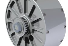
The use of two motors and an epicyclic gearing solves many challenges when trying to make a light and efficient propulsion system but adds complexity. The Nohassel design is an optimized compromise and is only useful when making a multi-targeted design. On almost every aspect it will be beaten by simpler designs when only looking at a single parameter, i.e. it's not: the lightest, strongest, most efficient, most cost efficient or smallest motor solution.
But it is probably the best compromise available by having:
Fully automatic transmission
Good torque - more than 100Nm on 26" wheel at hill clim speeds
High speed - 8000 RPM (80 km/h is possible without over-revving)
Sensorless reducing wiring and increasing reliability
No resistance while coasting up to 50 km/h
Efficient regen, even at low speed
Good weather protection
Low weight - less than 5kg/11lbs including batteries
DIY design reducing cost
Easy to install


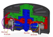
The functionality of the two motors is controlled electronically. The basic function is quite logical:
A) set the most powerful motor (LRK) to a speed that is within range of epicyclic gearing for the wheel RPM and optimized for LRK efficiency
B) set the speed of the smaller motor (HS) to a speed that matches LRK and wheel RPM (taken from a premade table in the master controllers program memory)
C) check if wheel speed is correct (based on sensor input from pedelec, brakes, throttle, current sensors, temperature sensors)
D) adjust target speed if needed and goto A)

There are some special cases:
1) Initiating sensorless LRK motor: The LRK is started running open-loop at a minimum speed. The HS will freewheel and the cycle will be stationary due to the HS motor not having much inertia. The HS will rotate backwards but will not brake since there is no current load.
2) Starting: The HS will be given a load by charging the battery as a generator. Increasing load will reduce the speed on the HS motor but the LRK speed is maintained by closed loop control so the output from the epicyclic will increase RPM and thus the speed of the cycle.
3) Coasting low-medium speed: The LRK will be more or less stationary and the HS will be free-wheeling up to 12000 RPM, having a coreless rotor it will not have iron loss and eddy losses should be very low due to stator being wound by very thin metal foil.
4) Coasting high-speed: The LRK is driven by voltage generated from HS to avoid over-revving the HS. Only enough energy to keep the LRK running is needed, thus low loss coasting should be possible at high speed.
5) Charging: The HS motor runs the cooling fan located on the motor axle. When charger or batteries get warm, the motor will need to start to prevent overheating. The LRK will run in oposite direction of the HS driven fan to keep the bicycle stationary. This has to be tightly controlled closed loop to prevent cycle from creeping slowly away.

Please find more info in the FAQ at the Nohassel development group: http://groups.google.com/group/nohassel

If anyone would like to join this open-source (and open-hardware) development, we could do with some more people. We need good engineering resources, especially for optimizing electromagnetic design of the motors, and helping out on the electronics design as we are designing our own dsPIC33f based motor controller.

Cheers,
Per
 
http://veloteq.com/veloteqgallery.com/c ... chart1.htm

The ECVT referred to on the Gulf Coast Veloteq web site is a term that was intended to describe the function of Electronic Controlled Variable Transmission whereby the electric motor torque is automatically varied dependent on that needed to enable the vehicle to attain cruising speed or surmont inclines, whereafter the torque is reduced to a lower level in order to conserve power. This is a function of feedback to the motor controller, not a function of the transmission itself. Although the hub motor which incorporates this technology is still in use, the newer Veloteq scooter type electric bicycles use a lower powered, 500W internal geared transmission motor which is capable of much higher torque, enabling a faster getaway and better hill climbing ability. It is easily capable of attaining the maximum speed of 20 mph permitted by law for this category of electric vehicle. This is achieved, however, with some sacrifice of efficiency. It does not consitute the hub of the rear wheel, but is attached along side the hub. The reference to the ECVT has been removed from up to date specifications to avoide confusion with mechanical CVT systems.
 
Lapwing said:
You may in fact find the principle is patented by Solomon technologies already.

http://www.solomontechnologies.com/wheel.htm

I believe there was a lawsuit a while back against Toyota for patent infringement. Not sure what happened.

It seems that this patent is invalid. At least in several countries like UK and Sweden, where the legal status is: "THE PATENT HAS BEEN ANNULLED BY A DECISION OF A NATIONAL AUTHORITY". More info can be found at http://v3.espacenet.com/publication...=A1&FT=D&date=19930908&DB=EPODOC&locale=en_EP

Unfortunately, the US patent authorities seems to approve almost every patent application they receive. This will for certainty destroy the international patent system :cry:
 
Back
Top